
Distance measuring method and distance measuring device

a distance measurement and distance measurement technology, applied in the direction of distance measurement, measurement gauges, instruments, etc., can solve the problems of serious error in the value of the measured distance, decreased /n ratio of the reflected light from the object to be measured, and deviation in the timing of detection, so as to achieve higher measurement accuracy and reduce power consumption. , the effect of improving the accuracy of measuremen

Inactive Publication Date: 2008-06-03
KK TOPCON
View PDF10 Cites 13 Cited by
  • Summary
  • Abstract
  • Description
  • Claims
  • Application Information

AI Technical Summary

Benefits of technology

[0011]It is an object of the present invention to provide a scanning type electro-optical distance measuring method and a scanning type electro-optical distance measuring device, by which it is possible to average the influence of speckle pattern on a luminous flux cross-section of a distance measuring light and to increase measurement accuracy without increasing the light intensity.

Problems solved by technology

As a result, deviation occurs in the timing of detection.
If there is phase deviation in the reflected distance measuring light 6, serious error may occur in the value of the measured distance.
Further, if the distance measuring light used for distance measurement does not have a certain predetermined light intensity, S / N ratio of the reflected light from the object to be measured is decreased, and this results in the problem of lower measurement accuracy.

Method used


Image

  • Distance measuring method and distance measuring device
  • Distance measuring method and distance measuring device
  • Distance measuring method and distance measuring device

Examples


Embodiment Construction

[0033]Description will be given below on the best mode for carrying out the present invention referring to the attached drawings.

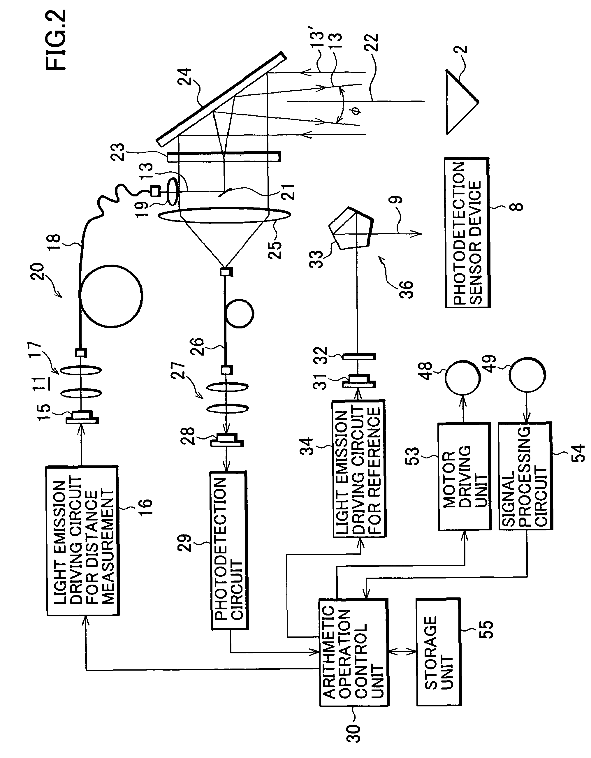
[0034]First, referring to FIG. 1 to FIG. 4, description will be given on general features of a scanning type distance measuring device, in which the present invention is carried out.

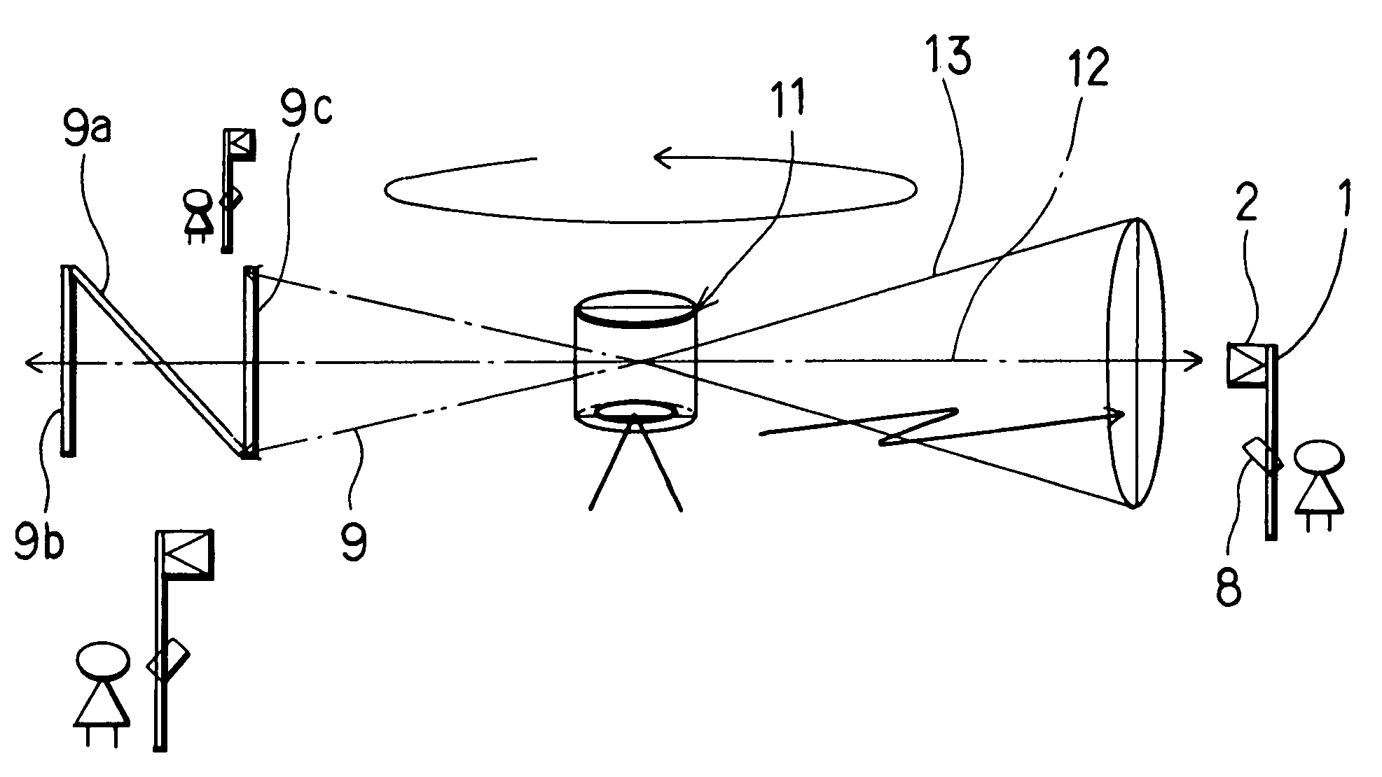
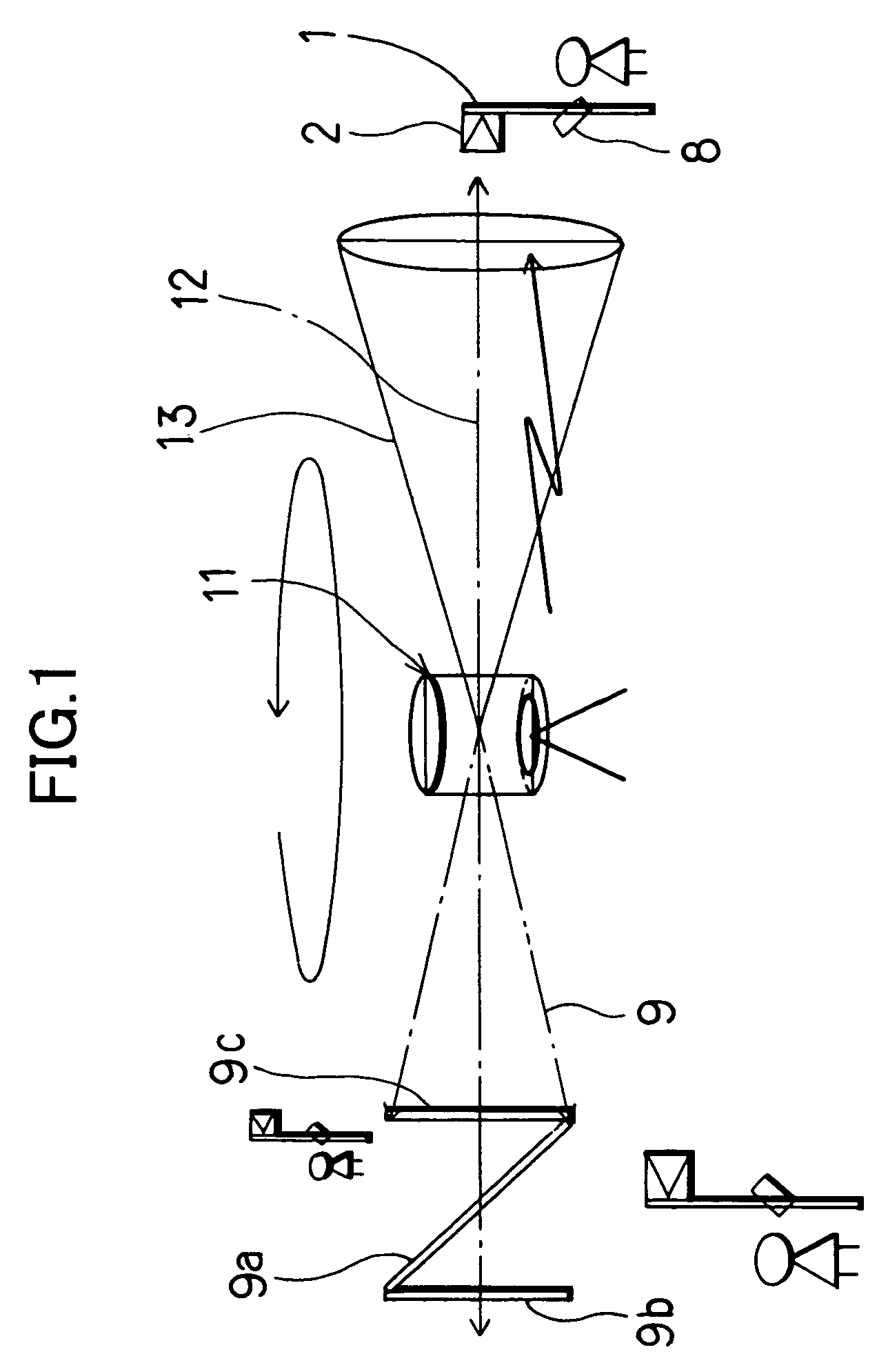
[0035]In an embodiment of the present invention, an object 2 to be measured is a prism for distance measurement mounted on a pole 1, which is held by an operator. A photodetection sensor device 8 for receiving a laser beam 9 for distance measurement reference plane (to be described later) is mounted on the pole 1.

[0036]A distance measuring device 11 as shown in FIG. 1 comprises a distance measuring unit (to be described later) and a distance measurement reference plane setting unit (not shown). The distance measuring device 11 projects the laser beam 9 for distance measurement reference plane by rotary irradiation and can project a distance measuring light 13 by rotary irradiat...


PUM


Abstract

A distance measuring method for performing distance measurement by projecting a distance measuring light to an object to be measured and by receiving a reflected light, comprising: a step of projecting for scanning the distance measuring light which has at least one luminous flux with a predetermined spreading angle; a step of emitting the light by pulsed light emission at least two times during a period when the luminous flux traverses the object to be measured; a step of measuring a distance by receiving the reflected light at least two times; and a step of averaging the results of the distance measurement.

Description

BACKGROUND OF THE INVENTION[0001]The present invention relates to a distance measuring method and a distance measuring device for measuring a distance by projecting a laser beam as a distance measuring light to an object to be measured and by receiving a reflection light from the object to be measured. In particular, the present invention relates to a distance measuring method and a distance measuring device for projecting the distance measuring light for scanning.[0002]When a distance to an object to be measured is measured by projecting a laser beam as a distance measuring light toward the object to be measured and by using a reflected light from the object to be measured, two methods are known as a distance measuring method: a collimation type electro-optical distance measuring method for performing distance measurement to the object to be measured on 1:1 basis, and a scanning type electro-optical distance measuring method for performing distance measurement by receiving a reflec...

Claims


Application Information

Patent Timeline
Patent Type & Authority Patents(United States)
IPC IPC(8): G01B3/36
CPCG01C15/002
Inventor OHTOMO, FUMIOOHISHI, MASAHIROISHINABE, IKUOSHIDA, KAZUHIRO
Owner KK TOPCON
Learn More