Liquid zoom lens

a zoom lens and liquid technology, applied in the field of liquid zoom lens, can solve the problems of distorted object shape, inability to provide high resolution, and various kinds of aberrations

Inactive Publication Date: 2008-06-03
SAMSUNG ELECTRO MECHANICS CO LTD
View PDF5 Cites 40 Cited by
  • Summary
  • Abstract
  • Description
  • Claims
  • Application Information

AI Technical Summary

Benefits of technology

[0026]An advantage of the present invention is that it provides a liquid zoom lens that can provide the optical zoom function and the auto-focus function at the same time. In the liquid zoom lens, one pair of aspheric lenses is mounted inside a cylindrical body. An electrolyte layer and an insulating liquid layer surround the aspheric lenses and form a plurality of interfaces. As the curvatures of the electrolyte layer and the insulating liquid layer are sequentially varied by the applied voltage, the optical zoom function and the auto-focus function can be achieved at the same time.
[0027]Additional aspect and advantages of the present general inventive concept will be set forth in part in the description which follows and, in part, will be obvious from the description, or may be learned by practice of the general inventive concept.
[0028]According to an aspect of the invention, a liquid zoom lens includes: a cylindrical body having upper and lower openings to which one pair of glass lenses is coupled; an auto-focus lens part including a first insulating liquid layer, a first electrolyte layer, and a first lens, which form an interface at a lower portion of the body; and an optical zoom lens part including a second insulating liquid layer, a second electrolyte layer, and a second lens, the second insulating liquid layer and the second electrolyte layer being disposed to form an immiscible interface on the first lens.
[0029]According to another aspect of the present invention, disk-like glass lenses are fixedly attached to the upper and lower openings of the body. A plurality of liquid layers and lenses form a plurality of interfaces within the body, and are embedded into the portable terminal.
[0030]According to a further aspect of the present invention, the body may be formed of the same material as the body of the portable terminal, or may be formed of metal or ceramic. The body has a metal coating layer in the inner periphery such that it can act as an electrode. It is preferable that the coating surface is formed of gold (Au) that is less reactive to liquid.
[0031]According to a still further aspect of the present invention, the auto-focus lens part and the optical zoom lens part stacked in the inside of the body include the insulating liquid layer, the electrolyte layer and the lens in the multi-layer structure, thus forming a plurality of interfaces. The insulating liquid layer and the electrolyte layer of the auto-focus lens part are separated from the optical zoom lens part by the first lens whose outer periphery is closely attached to the inner lower portion of the body.

Problems solved by technology

In such a lens system, various kinds of aberrations are caused by incident light having different wavelengths when taking the image.
The aberration causes the shape of the object to be distorted.
Thus, the digital zoom is advantageous to the miniaturization and slim profile, but it cannot provide the high resolution.
Consequently, there occurs the problem that a large space for the zoom function is occupied in the inside of the camera.
Power is dissipated in driving the motor and thus power dissipation of the battery increases.
Furthermore, the conventional liquid lens has a complex structure.
Consequently, the structure of the liquid lens becomes more complex.

Method used


Image

  • Liquid zoom lens
  • Liquid zoom lens
  • Liquid zoom lens

Examples


Embodiment Construction

[0041]Reference will now be made in detail to the embodiments of the present general inventive concept, examples of which are illustrated in the accompanying drawings, wherein like reference numerals refer to like elements throughout. The embodiments are described below in order to explain the present general inventive concept by referring to the figures.

[0042]Structure of Liquid Zoom Lens

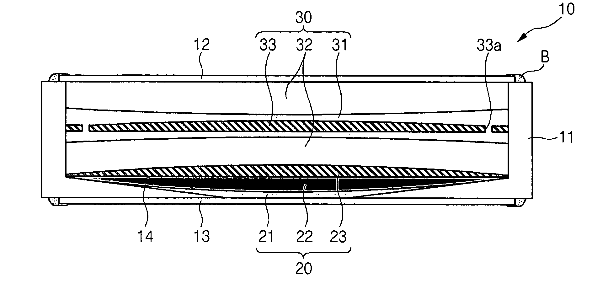
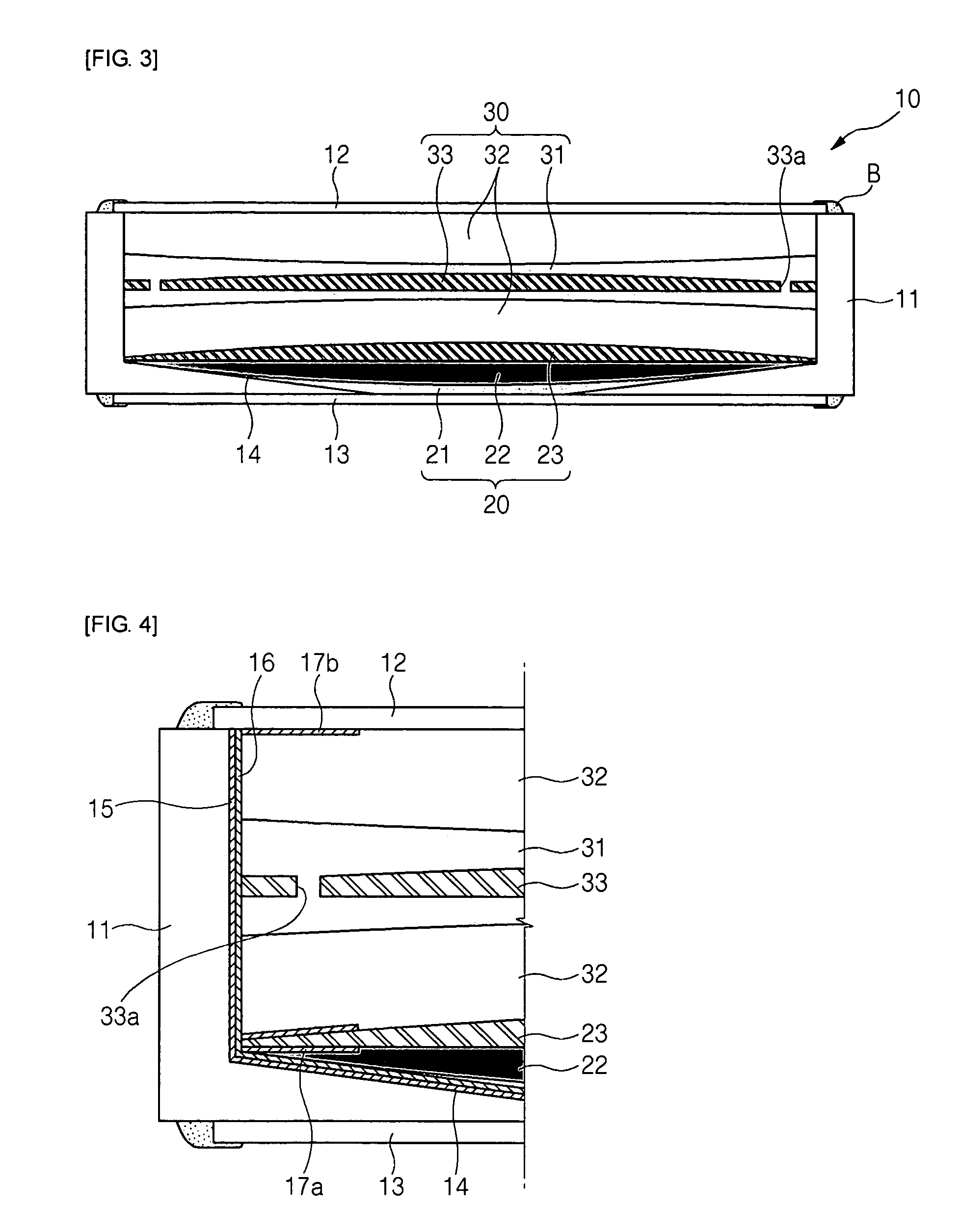
[0043]FIG. 3 is a sectional view of a liquid zoom lens according to the present invention, and FIG. 4 is a partially enlarged sectional view of a body of the liquid zoom lens illustrated in FIG. 3. Referring to FIGS. 3 and 4, the liquid zoom lens 10 includes a cylindrical body 11, an auto-focus lens part 20, and an optical zoom lens part 30. Glass lenses 12 and 13 are fixedly attached to upper and lower openings of the cylindrical body 11. A plurality of electrolyte layers 22 and 32 and insulating liquid layers 21 and 31 having different physical properties form a plurality of interfaces within the...


PUM


Abstract

A liquid zoom lens mounted on a portable terminal is provided. In the liquid zoom lens, a cylindrical body has upper and lower openings to which one pair of lenses is coupled. An auto-focus lens part includes a first insulating liquid layer, a first electrolyte layer, and a first lens. The first insulating layer and the first electrolyte layer are disposed to form an interface at a lower portion of the body. The first lens is disposed on the first electrolyte layer and has a periphery closely attached to a lower portion of an inner periphery of the body. An optical zoom lens part includes a second insulating liquid layer, a second electrolyte layer, and a second lens. The second insulating liquid layer and the second electrolyte layer are disposed to form an interface on the first lens. The second lens is fixed to be movable within the second insulating liquid layer, such that a periphery is closely attached to the inner periphery of the body. Accordingly, the auto-focus function and the optical zoom function can be simultaneously achieved through a single liquid lens whose curvature is varied by the difference of the inherent refractive index between the electrolyte and the insulating liquid.

Description

CROSS-REFERENCE TO RELATED APPLICATIONS[0001]This application claims the benefit of Korean Patent Application No. 2005-103790 filed with the Korea Industrial Property Office on Nov. 1, 2005, the disclosure of which is incorporated herein by reference.BACKGROUND OF THE INVENTION[0002]1. Field of the Invention[0003]The present invention relates to a liquid zoom lens for a portable terminal, and more particularly, to a liquid zoom lens that can provide an optical zoom function and an auto-focus function at the same time. In the liquid zoom lens, when a voltage is applied to the inside of a cylindrical body, the curvature of electrolyte and insulating liquid is varied. The electrolyte and the insulating liquid form a plurality of interfaces. Aspheric lenses are sequentially mounted to contact the interfaces or in the insulating liquid. The optical zoom function and the auto-focus function are achieved at the same time by the curvature variation of the electrolyte around the aspheric len...

Claims


Application Information

Patent Timeline
Patent Type & Authority Patents(United States)
IPC IPC(8): G02B3/12G02B1/06G02B3/14G02B7/02G02B7/04G02B7/09G02B7/28G02B13/18G02B15/00
CPCG02B1/06G02B3/14G02B13/0045G02B13/006G02B13/0075G02B13/009G02B26/005G02B3/12
Inventor JUNG, HA YONGBAE, JAE YOUNGKIM, SUNG CHANYANG, JIN HYUCKLEE, YOUNG HO
Owner SAMSUNG ELECTRO MECHANICS CO LTD
Why Eureka
Try Eureka