Variable magnification optical system

a magnification optical system and variable magnification technology, applied in the field of variable magnification optical systems, can solve the problems of difficult to ensure optical performance to meet such high-standard specifications, difficult to use conventional zoom lens systems, and large image-taking lens systems, etc., to achieve high magnification variation ratio, high performance, and compact size

a magnification optical system and variable magnification technology, applied in the field of variable magnification optical systems, can solve the problems of difficult to ensure optical performance to meet such high-standard specifications, difficult to use conventional zoom lens systems, and large image-taking lens systems, etc., to achieve high magnification variation ratio, high performance, and compact size

US7382548B2Inactive Publication Date: 2008-06-03KONICA MINOLTA PHOTO IMAGING

Image

  • Variable magnification optical system
  • Variable magnification optical system
  • Variable magnification optical system

Examples


examples

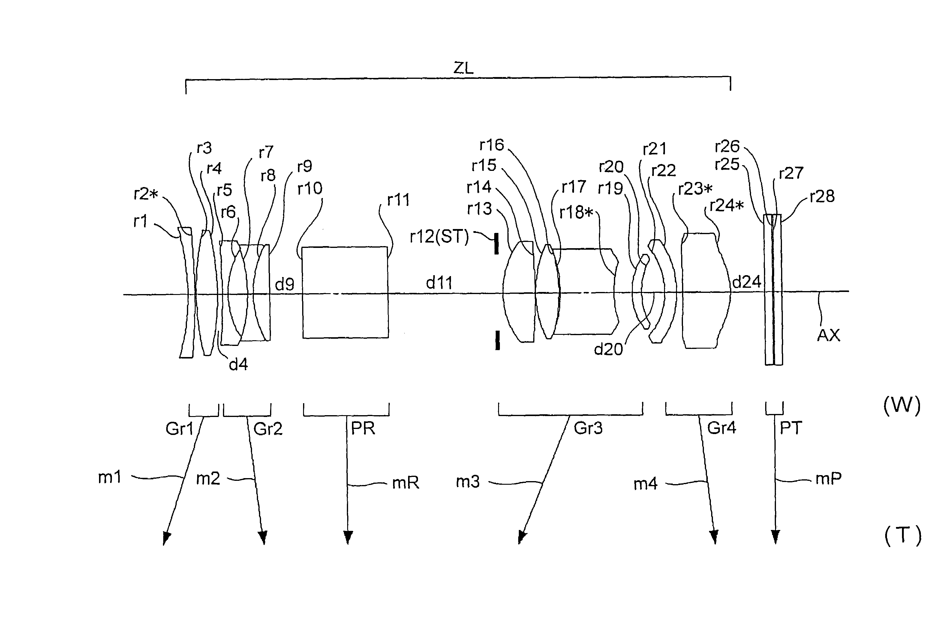
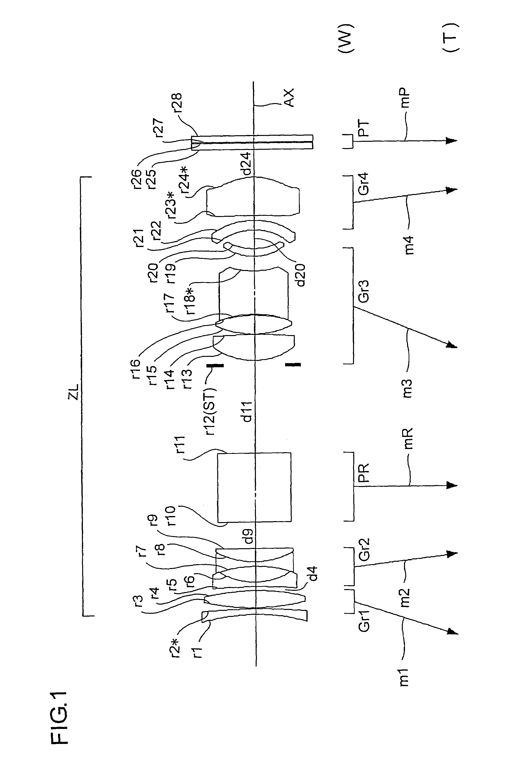
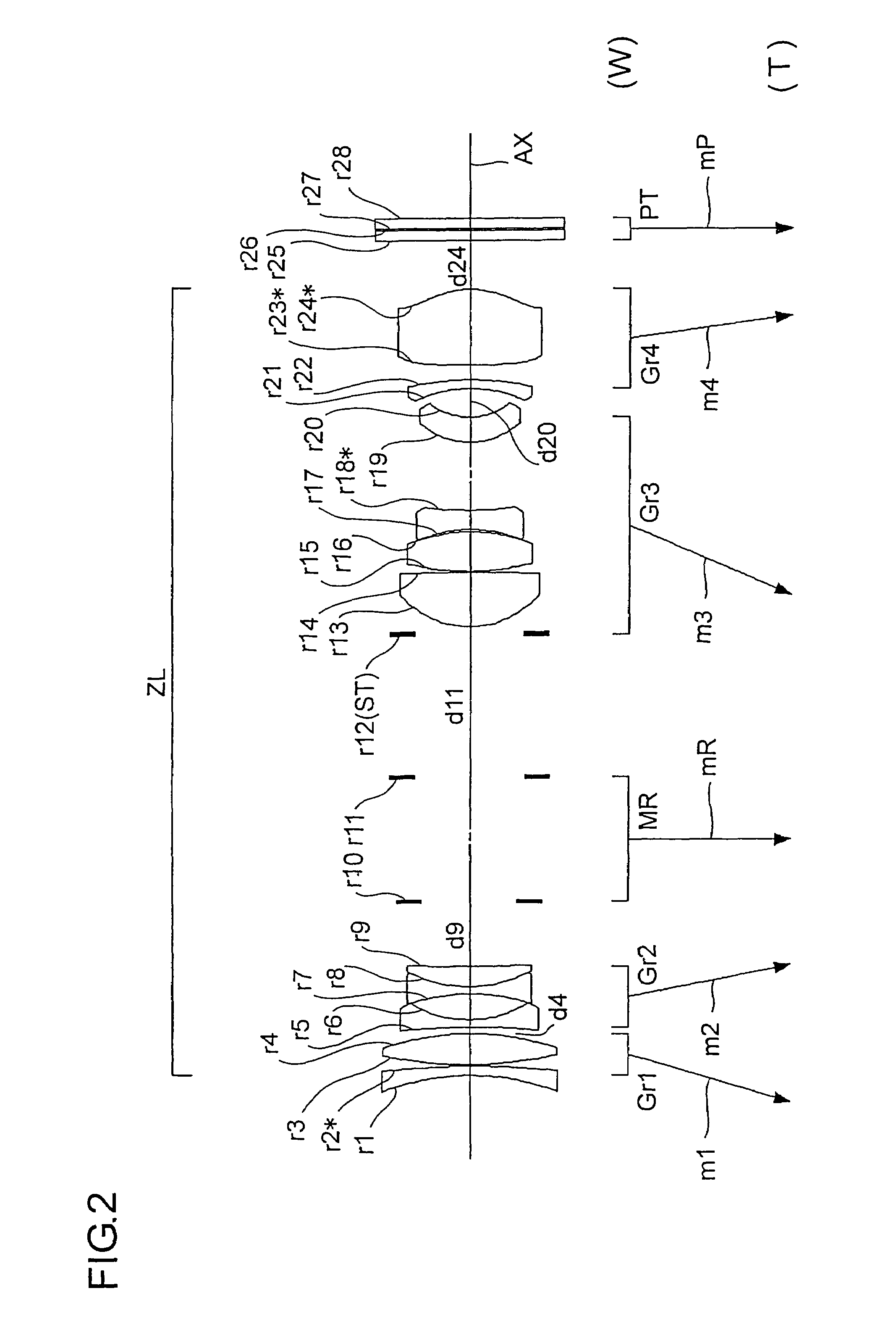
[0140]Hereinafter, practical examples of the zoom lens system embodying the present invention will be presented with reference to their construction data and other data. Examples 1 to 5 presented below are numerical examples corresponding respectively to the first to fifth embodiments described above. Thus, the optical construction diagrams (FIGS. 1 to 5) showing the first to fifth embodiments also show the lens constructions of Examples 1 to 5, respectively.

[0141]Tables 1 to 10 show the construction data of Examples 1 to 5. Table 11 shows the values for the conditional formulae, etc., as actually observed in each example. In the basic optical construction shown in Tables 1, 3, 5, 7, and 9 (where i represents the surface number), ri (i=1, 2, 3, . . . ) represents the radius of curvature (in mm) of the i-th surface counted from the object side; di (i=1, 2, 3, . . . ) represents the axial distance (in mm) between the i-th and (i+1)th surfaces counted from the object side; Ni (i=1, 2, ...


PUM


Abstract

A variable magnification optical system of the present invention for forming an optical image of an object on a light-receiving surface of an image sensor with variable magnification includes: from the object side, at least a first lens unit having a positive optical power, a second lens unit having a negative optical power, a third lens unit having a positive optical power, and a fourth lens unit having a positive optical power. The variable magnification is performed by movement of at least the first lens unit and the third lens unit. A bending optical element for bending an optical axis is provided between the second lens unit and the third lens unit. Moreover, prescribed conditional formulae are fulfilled.

Description

[0001]This application is based on Japanese Patent Application No. 2005-205545 filed on Jul. 14, 2005, the contents of which are hereby incorporated by reference.BACKGROUND OF THE INVENTION[0002]1. Field of the Invention[0003]The present invention relates to a variable magnification optical system. More particularly, the present invention relates to a variable magnification optical system (especially a compact zoom lens system that offers high magnification variation) suitable for, for example, a digital camera and a digital appliance equipped with an image capturing capability that capture an image of a subject with an image sensor, and to an image-taking apparatus provided therewith.[0004]2. Description of Related Art[0005]Due to recent widespread use of digital cameras, silver salt cameras seem to have been replaced with these digital cameras. Following the widespread use of digital cameras, there has been a demand for an even more compact digital camera and also a demand for an ...

Claims


Application Information

Patent Timeline
03 Jun 2008
Publication
US7382548B2
IPC
G02B15/14; G02B17/00
CPC
G02B15/173; G02B15/144113; G02B15/16
Inventors
KOHNO, TETSUO; YAGYU, GENTA