Control system and method for rewriting data in a flash memory and a data storage medium in which a program is stored for rewriting data in a flash memory

a control system and data storage technology, applied in program control, memory adressing/allocation/relocation, instruments, etc., can solve the problems of time-consuming, time-consuming, and complicated rewrite process, so as to reduce the time required and the incidence of errors in the rewrite process. , the effect of simplifying the rewrite process

Inactive Publication Date: 2008-06-03
SEIKO EPSON CORP
View PDF50 Cites 15 Cited by
  • Summary
  • Abstract
  • Description
  • Claims
  • Application Information

AI Technical Summary

Benefits of technology

[0011]The present invention provides a control system and method that simplifies rewriting flash memory and reduces the time required and the incidence of errors in the rewrite process while also preventing the elec

Problems solved by technology

As described above, rewriting data stored in the boot memory portion of the flash memory cannot be completed w

Method used


Image

  • Control system and method for rewriting data in a flash memory and a data storage medium in which a program is stored for rewriting data in a flash memory
  • Control system and method for rewriting data in a flash memory and a data storage medium in which a program is stored for rewriting data in a flash memory
  • Control system and method for rewriting data in a flash memory and a data storage medium in which a program is stored for rewriting data in a flash memory

Examples


embodiment 1

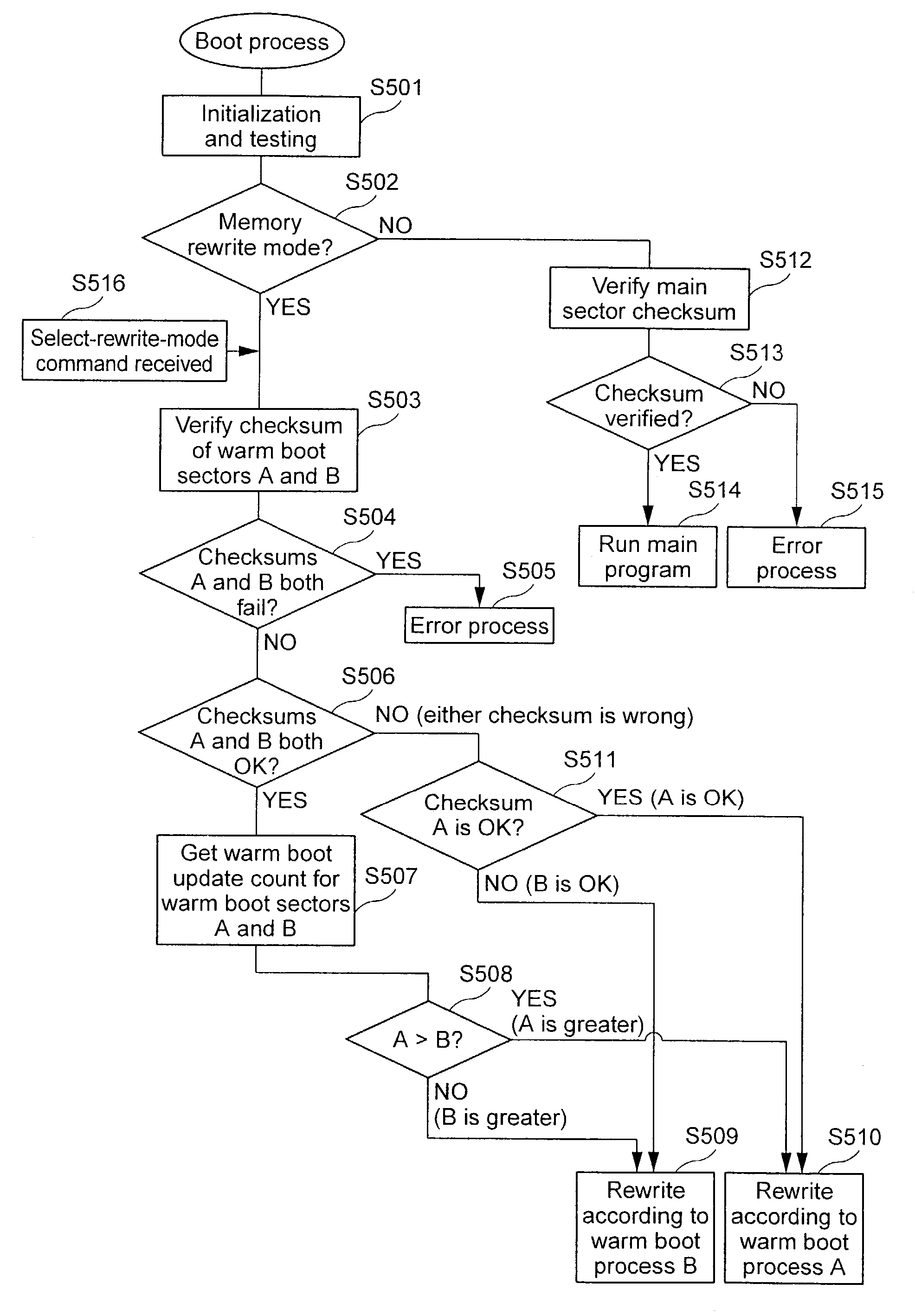
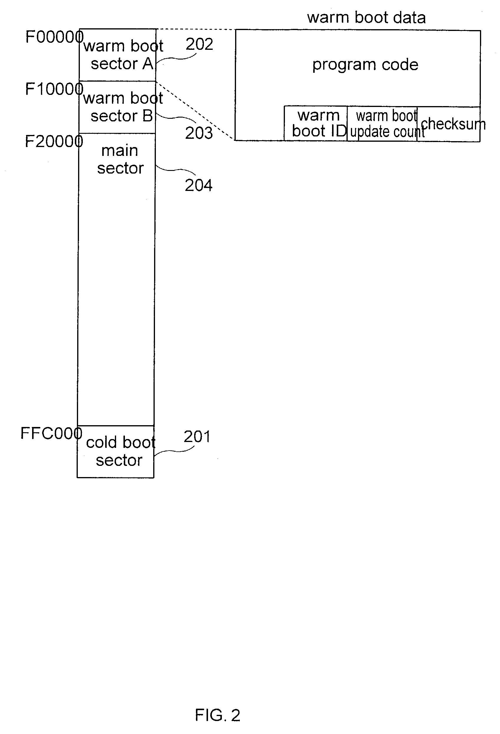
[0036]FIG. 2 shows an example of the sector configuration of a flash memory device. This configuration is described below using a boot memory portion comprising three sectors by way of example. The three sectors forming the boot memory portion of flash memory 101 are first boot sector 201, a second boot sector 202, and a third boot sector 203. The second and third boot sectors are also hereinafter referred to as the warm boot sectors.

[0037]Boot data required to implement the minimum functions needed to boot the electronic device is stored in the first boot sector 201. These minimum functions may include, for example, initializing the CPU 103 and the stack, a write / read test of the RAM 102 and other tests such as a write / read test of a gate array register (not shown), and evaluations such as a boot mode evaluation. The first boot sector 201 is also hereinafter called the “cold boot sector”, The data stored in the cold boot sector 201 is called the “cold boot data”, and the process ru...

embodiment 2

[0094]This second embodiment of the invention differs from the first embodiment above in that it can rewrite the cold boot sector 201 in addition to warm boot sectors A 202 and B 203 and the main memory portion 204. This difference between the second and first embodiments is described below.

[0095]A danger with rewriting the cold boot data stored in the cold boot sector 201 is that a write error, for example, could render the electronic device unbootable. To avoid this problem in the first embodiment above the cold boot sector cannot be rewritten and only warm boot sectors 202, 203 and the main memory portion 204 are rewritable sectors, thereby protecting the cold boot data. This is referred to as the “normal rewrite mode” below. The cold boot process is composed of the minimal functions needed to boot the electronic device, thereby reducing the potential need to rewrite the cold boot data. It may still be necessary to rewrite the cold boot data, however, in order to correct bugs in ...


PUM


Abstract

A memory control system and method for controlling the rewriting of data in a flash memory which includes a boot memory portion having a plurality of sectors including a boot sector for storing cold boot data, N other boot sectors for storing other boot data and having a program process in each of said N boot sectors for rewriting data in boot sectors other than itself and other than said cold boot sector based upon the boot data stored therein. The control system further includes a boot data evaluation unit for recognizing which of the boot sectors has been most recently updated with update data and which program process is to be used for rewriting data in boot sectors other than itself and a rewrite unit for rewriting data.

Description

BACKGROUND OF THE INVENTION[0001]1. Field of the Invention[0002]The present invention relates to a control system and method for rewriting data in a flash memory storing both a boot program and a main program as firmware of an electronic device and to a data storage medium in which a program is stored for rewriting data in a flash memory.[0003]2. Description of Related Art[0004]The boot program and the main program of the firmware in printers, scanners, and other such electronic devices are separate programs typically stored in flash memory. In a printer, for example, the main program controlling the normal operation of the printer, i.e., the printing process, and font data are stored in a main memory portion of the flash memory. The program for running the boot program to initialize the printer, and a program for controlling a memory rewrite process for writing to the flash memory are stored in a boot memory portion of the flash memory. The rewrite process is used to rewrite to the...

Claims


Application Information

Patent Timeline
IPC IPC(8): G06F9/00G06F9/445
CPCG06F8/65G06F9/4401G06F12/02
Inventor TAKAMIZAWA, YUJIHIROIKE, GO
Owner SEIKO EPSON CORP
Why Eureka
Try Eureka