Rotatable and telescopic work machine

a work machine and telescopic technology, applied in mechanical machines/dredgers, manufacturing tools, tractors, etc., can solve the problems of reducing the efficiency or performance limiting the ability of the work machine to enter certain work areas, and reducing so as to improve operator visibility, reduce the overall height of the work machine, and easy access

Inactive Publication Date: 2008-06-10
JLG IND INC
View PDF91 Cites 16 Cited by
  • Summary
  • Abstract
  • Description
  • Claims
  • Application Information

AI Technical Summary

Benefits of technology

[0011]The present invention is a rotatable work machine that includes a lower frame assembly having an open area in which the operator portion of an upper frame assembly and power source are at least partially positioned. This serves to reduce the overall height of the work machine to the point where it can easily access enclosed work areas or buildings having space constrained entryways. Additionally, specific positioning of the various components at a lower level on the work machine provides a low center of gravity with improved operator visibility. Further, the manufacturing and assembly of the work machine is such that costs and complexity are reduced.

Problems solved by technology

The significant height of the work machine limits its ability to enter certain work areas or buildings that have space constraints at access doors, service entries, and the like.
Further, the positioning of the various components on some of these work machines causes weight distribution problems as the center of gravity is elevated and focused.
Weight distribution problems can reduce efficiency or performance of the work machine.
Additionally, an elevated center of gravity reduces stability of the work machine and reduces operator visibility as the various components are placed at higher levels.
Visibility may be further impaired on some of these work machines when the telescopic boom is mounted on one side of the cab and blocks the operator's view of a work implement, attached to the telescopic boom, or the surrounding terrain.
Although the positioning of a portion of the upper works within the well assists in lowering the center of gravity of the crane, the positioning of the engine above the chassis distributes weight at an elevated level that nullifies the low center of gravity benefits.
Additionally, the positioning of the engine rearward of the boom support may create an unfavorable distribution of weight at the rear of the crane, lowering its efficiency and stability.
Further, the positioning of the engine in such a manner results in a low clearance height for the swing radius of the boom and effectively blocks all rear visibility for the operator during operation of the crane.
Other rotatable work machines that do not have telescopic booms, such as excavators, may also have similar deficiencies as those work machines with telescopic booms.
While this may not be as great an issue in a rotatable excavator that typically works in an external environment, any increase of height in a rotatable and telescopic work machine lowers its accessibility to enclosed work areas or buildings that have space constrained entryways.

Method used


Image

  • Rotatable and telescopic work machine
  • Rotatable and telescopic work machine
  • Rotatable and telescopic work machine

Examples


Embodiment Construction

[0021]While the invention is open to various modifications and alternative forms, a specific embodiment thereof has been shown by way of example in the drawings and will herein be described in detail. However, there is no intent to limit the invention to the particular form disclosed.

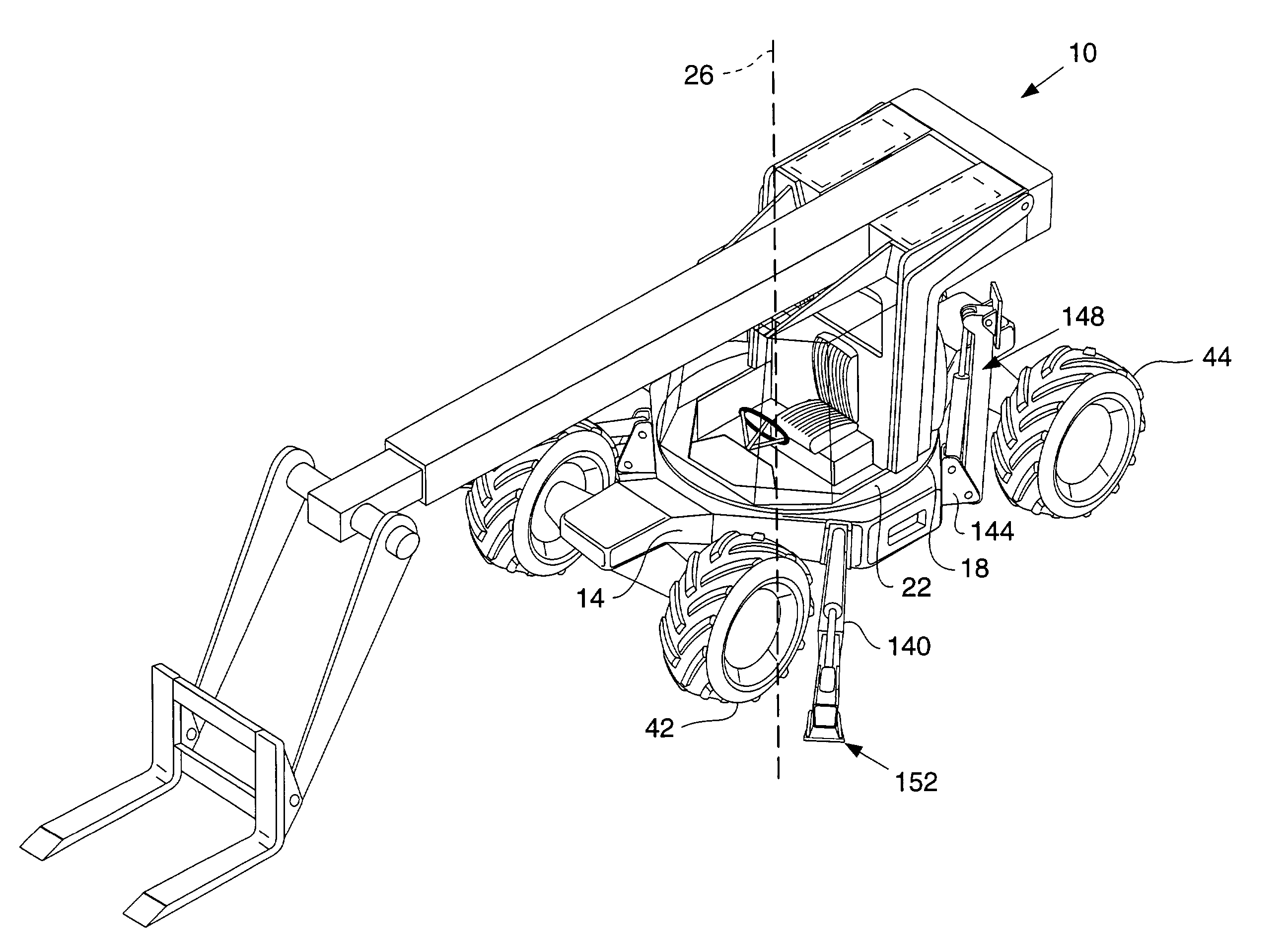
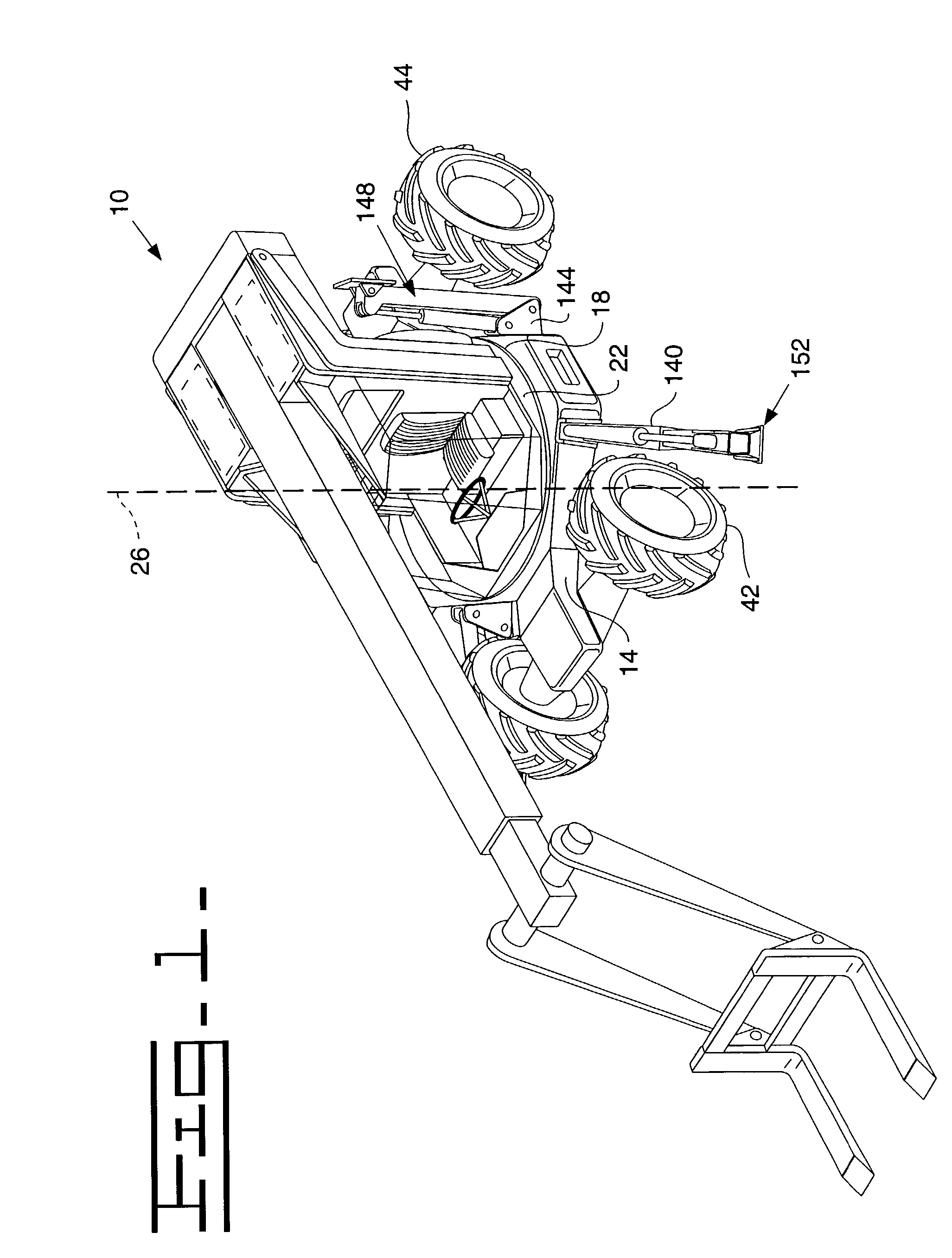
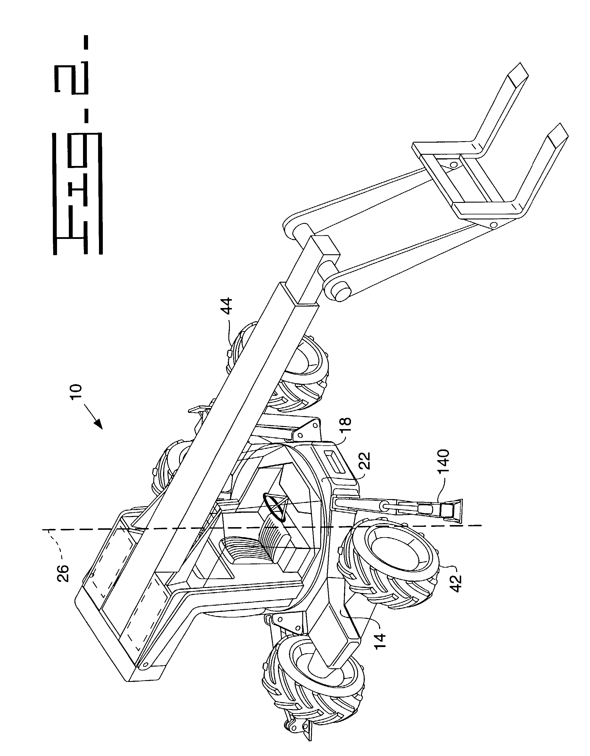
[0022]Referring to the drawings, a rotatable and telescopic work machine 10 is shown. It should be understood that although the work machine shown includes telescopic capabilities, any work machine having an upper rotatable portion is conceivably within the scope of the invention. The work machine 10 has a front end portion 14, a rear end portion 18 and a central portion 22 through which a vertical axis 26 extends.

[0023]The work machine 10 includes a mainframe assembly 34, seen best in FIGS. 3-4, that is supported against the ground 38 by driving means, such as a pair of front and rear wheels 42,44. It should be understood that any suitable driving means, such as a metallic or rubber track, might be uti...


PUM

PropertyMeasurementUnit
heightaaaaaaaaaa
heightaaaaaaaaaa
swing radius heightaaaaaaaaaa

Abstract

The present invention is a rotatable work machine that includes a lower frame assembly having a recessed area in which the operator portion of an upper frame assembly and power source are at least partially positioned. Further, a method of manufacturing and assembling the lower frame assembly enables various size configurations for the work machine. The method of manufacturing and assembling the work machine, along with the specific design and positioning of the various components therein, enhances stability, clearance, and operator visibility with reduced costs and complexity.

Description

TECHNICAL FIELD[0001]This invention relates generally to a rotatable and telescopic work machine and, more particularly, to a rotatable and telescopic work machine having a low clearance height, a low center of gravity, and unobstructed operator visibility.BACKGROUND[0002]In current rotatable and telescopic work machines, such as material handling machines, the overall height of the work machine is generally increased due to the “stacking” of various components, such as, the rotation means, cab, engine and telescopic boom. The significant height of the work machine limits its ability to enter certain work areas or buildings that have space constraints at access doors, service entries, and the like. Further, the positioning of the various components on some of these work machines causes weight distribution problems as the center of gravity is elevated and focused. Weight distribution problems can reduce efficiency or performance of the work machine. Additionally, an elevated center o...

Claims


Application Information

Patent Timeline
Patent Type & Authority Patents(United States)
IPC IPC(8): B62D33/00B66F9/065B66F9/075E02F3/28E02F9/02E02F9/08E02F9/12
CPCB66F9/0655B66F9/07545B66F9/07559E02F3/286E02F9/0808E02F9/0833E02F9/123E02F9/02Y10T29/49826
Inventor SEWELL, ANDREW J.
Owner JLG IND INC
Why Eureka
Try Eureka