Bearing cover for a crankshaft bearing of an internal combustion engine

a technology of internal combustion engine and bearing cover, which is applied in the direction of machine/engine, machine support, rigid support of bearing unit, etc., can solve the problems of insufficient optimization of the configuration of the bearing cover, insufficient optimization of the connection of the transverse rib with the introduction of round openings, and insufficient rigidity of the bearing cover. , to achieve the effect of high rigidity, low weight and high wear resistan

Inactive Publication Date: 2008-06-10
AUDI AG
View PDF12 Cites 10 Cited by
  • Summary
  • Abstract
  • Description
  • Claims
  • Application Information

AI Technical Summary

Benefits of technology

[0017]One advantageous configuration of the rib cross-section provides that the rib is to be less than half as wide as the bearing shell and that it is to extend in the center of the latter. A narrow configuration of the rib serves the purpose of high rigidity accompanied by low weight.
[0018]As has already been stated, the configuration of the bearing cover claimed for the invention is especially well suited for production from a homogeneous material; preference is to be given to use of cast iron with nodular graphite because of the high wear resistance and the high corrosion resistance.

Problems solved by technology

Because of the core, this bearing cover is costly to manufacture and its configuration is not optimized.
In particular, the connection of the transverse rib accompanied by introduction of the round openings has not been optimized from the viewpoint of force flow and material complexity and accordingly from that of weight as well.

Method used


Image

  • Bearing cover for a crankshaft bearing of an internal combustion engine
  • Bearing cover for a crankshaft bearing of an internal combustion engine
  • Bearing cover for a crankshaft bearing of an internal combustion engine

Examples


Embodiment Construction

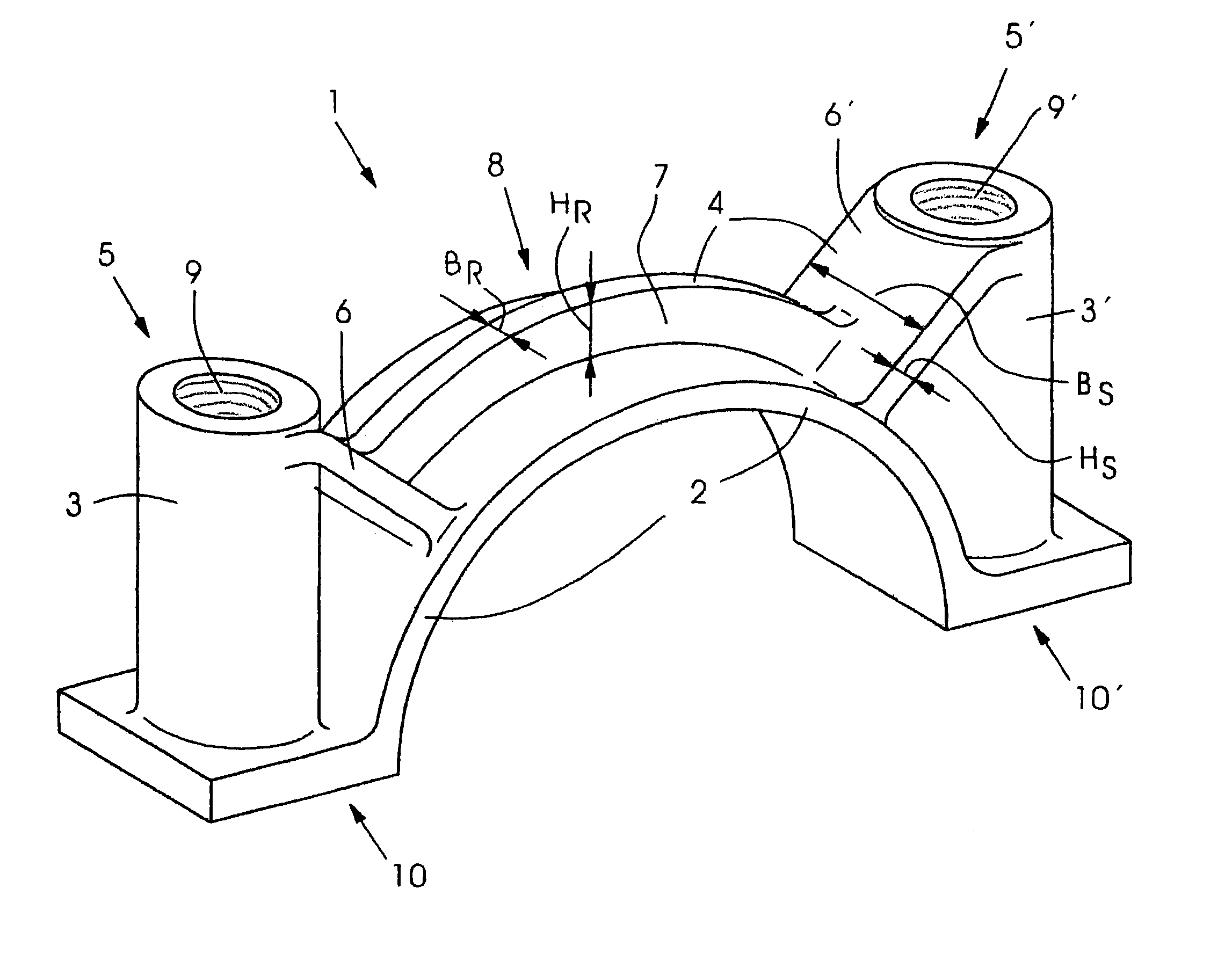
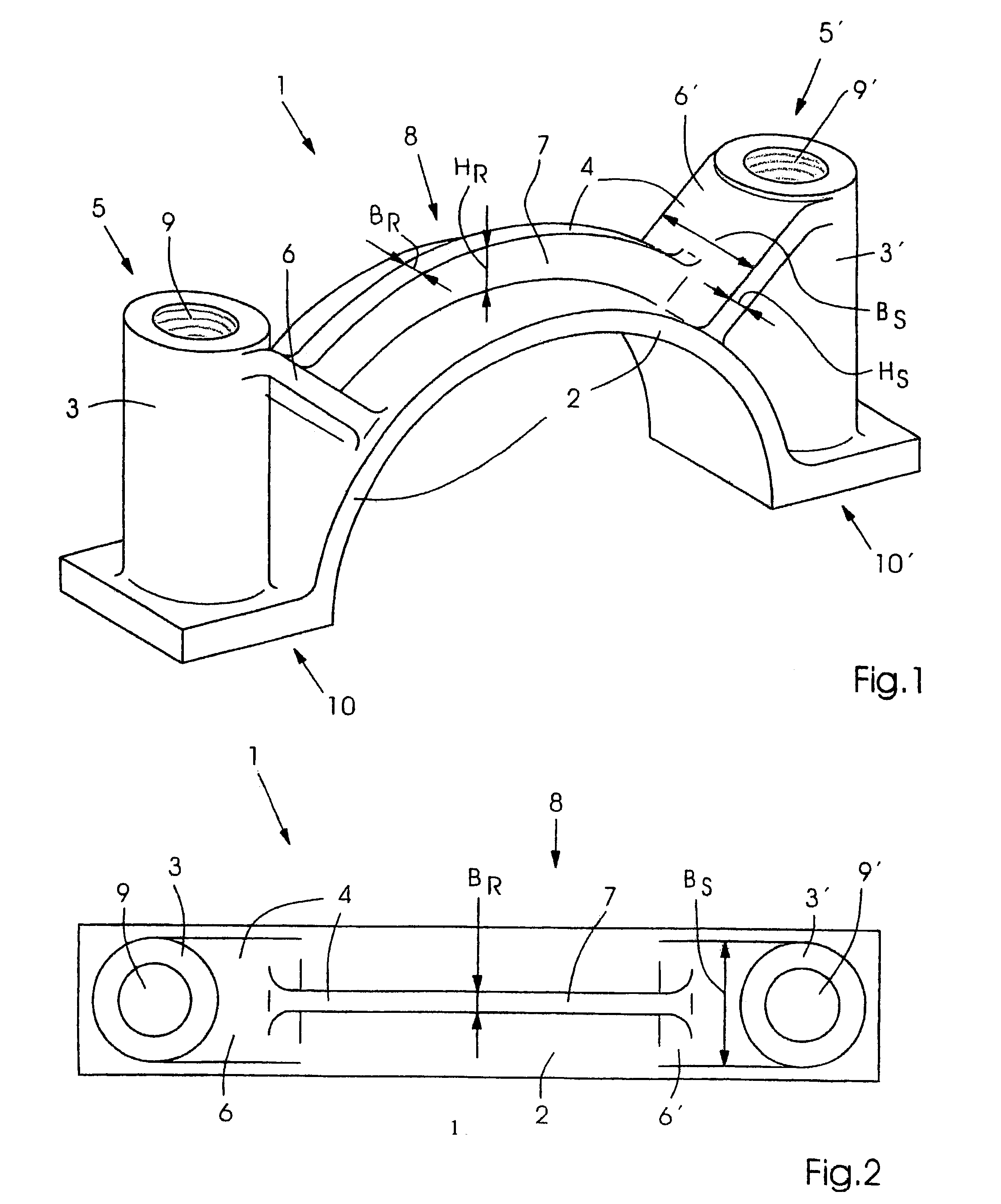
[0024]FIG. 1 shows a perspective view of an example of embodiment of the bearing cover 1 claimed for the invention. This cover consists of a semicircular bearing shell 2 with straight supports 10, 10′ for fastening the bearing cover 1 to a thrust bearing not shown. Threaded channels 3, 3′, which are provided with openings 9, 9′, extend upward from these supports 10, 10′.

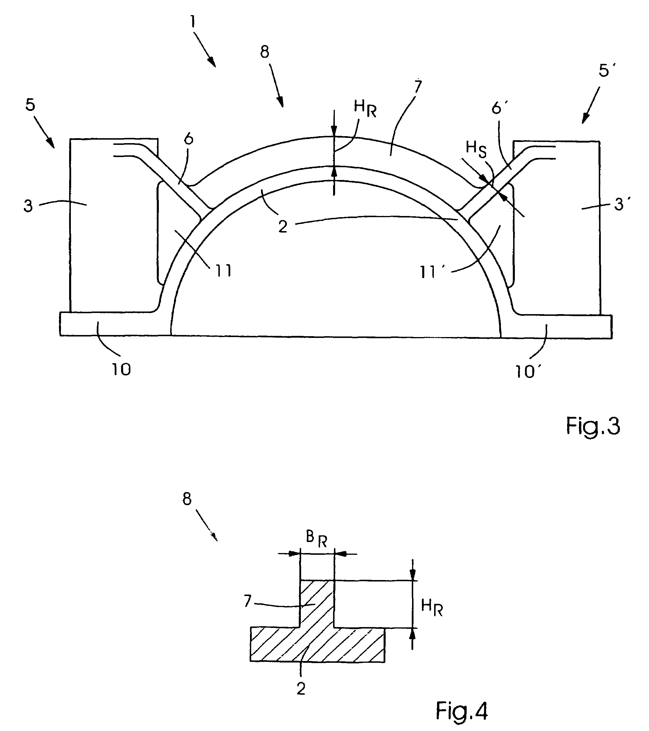
[0025]An essential feature claimed for the invention is the configuration of the brace 4, which stabilizes the bearing shell 2 between the two threaded channels 3, 3′. This brace 4 has struts 6, 6′ which extend obliquely from the upper area 5, 5′ of the threaded channels 3, 3′, are connected to the bearing shell 2, and have a height Hs and a width Bs. A rib 7 mounted on the top of the bearing shell 2 extends between these struts 6, 6′, so that the bearing shell 2 forms with the rib 7 a web 8 extending between the struts 6, 6′. The rib 7 has a width BR and a height HR.

[0026]In order to achieve an optimum force flow wi...


PUM


Abstract

The invention relates to a bearing cover (1) for a crankshaft bearing of an internal combustion engine comprising a bearing shell (2), two screw columns (3,3′), which are located on both sides of the bearing shell (2) and provided for mounting on a bearing block, and comprising a reinforcement (4) of the bearing shell (2) extending between both screw columns (3,3′). The aim of the invention is to optimize a bearing cover (1) of the aforementioned type with regard to its shape whereby attaining a high level of stability with a low weight. To this end, the reinforcement (4) is comprised of two braces (6,6′), which extend diagonally from the area of the upper ends (5,5′) of the screw columns (3,3′) to the bearing shell (2) and which have an essentially constant cross-section over the length thereof, and comprised of a rib (7) extending on the upper side of the bearing shell (2) from one brace (6) to the other (6′).

Description

FIELD OF THE INVENTION[0001]The invention relates to a bearing cover of an internal combustion engine having a bearing shell, two threaded channels mounted on the side of the bearing shell for fastening on a thrust bearing, and two braces of the bearing shell extending between the two threaded channels for fastening on a thrust bearing.BACKGROUND OF THE INVENTION[0002]A bearing cover such as this is disclosed in DE 34 26 208 C1. For the purpose of weight reduction, this bearing cover is made of a light metal alloy into which a core of a ferrous metal material is introduced, which core is extended to the threaded channels in the area of the crankshaft bearing and also encloses these channels. The brace is configured as a transverse rib between the threaded channels forming a double T shape with the core and having two round openings on the threaded channels. Because of the core, this bearing cover is costly to manufacture and its configuration is not optimized. In particular, the con...

Claims


Application Information

Patent Timeline
Patent Type & Authority Patents(United States)
IPC IPC(8): F16C35/00F02F7/00F16C9/02F16M1/025
CPCF02F7/0053F16C9/02F16C35/00F16M1/025F05C2201/0439
Inventor BINDER, THOMASMARKLE, TOBIAS
Owner AUDI AG
Why Eureka
Try Eureka