Differential transmission circuit and common mode choke coil

a transmission circuit and choke coil technology, applied in the direction of transformer/inductance magnetic core, line-transmission details, baseband system details, etc., to achieve the effect of improving signal noise elimination capability, excellent image quality, and eliminating nois

Inactive Publication Date: 2008-06-10
PANASONIC CORP
View PDF7 Cites 14 Cited by
  • Summary
  • Abstract
  • Description
  • Claims
  • Application Information

AI Technical Summary

Benefits of technology

[0018]When the differential transmission circuit has this structure, the first signal transmitted through the first transmission line passes through the common mode choke coil. The second signal transmitted through the second transmission line passes through the common mode choke coil. Furthermore, the noise carried in the first and second signals that pass through the first terminator and second terminator flows to the common mode choke coil. Then a counter electromotive force is generated by the noise carried in the first and second signals transmitted through the first transmission line and second transmission line, and a counter electromotive force is generated by the noise of the first and second signals flowing to the common mode choke coil through the first terminator and second terminator. Current corresponding to the generated electromotive force flows to the common mode choke coil and generates lines of magnetic flux, which eliminate the noise. Accordingly, the counter electromotive force generated in the common mode choke coil increases, and the lines of magnetic flux increase even when only signals transmitted through the first transmission line and second transmission line flow to the common mode choke coil. Therefore, there is an increase in the capability for eliminating the signal noise in the common mode choke coil, and inputting a large amount of noise to the semiconductor device can be prevented. Consequently, damage to the semiconductor device caused by excessive noise can be prevented, and signal noise is prevented from affecting other nearby devices.
[0045]When using the differential transmission circuit of the present invention, the counter electromotive force generated in the common mode choke coil is reinforced by means of a circuit structure which is both inexpensive and light weight. Accordingly, common mode noise can be eliminated and protection of the differential receiver improved even when there is excessive noise from external devices.

Problems solved by technology

Furthermore, the noise carried in the first and second signals that pass through the first terminator and second terminator flows to the common mode choke coil.

Method used


Image

  • Differential transmission circuit and common mode choke coil
  • Differential transmission circuit and common mode choke coil
  • Differential transmission circuit and common mode choke coil

Examples


first embodiment

(1) First Embodiment

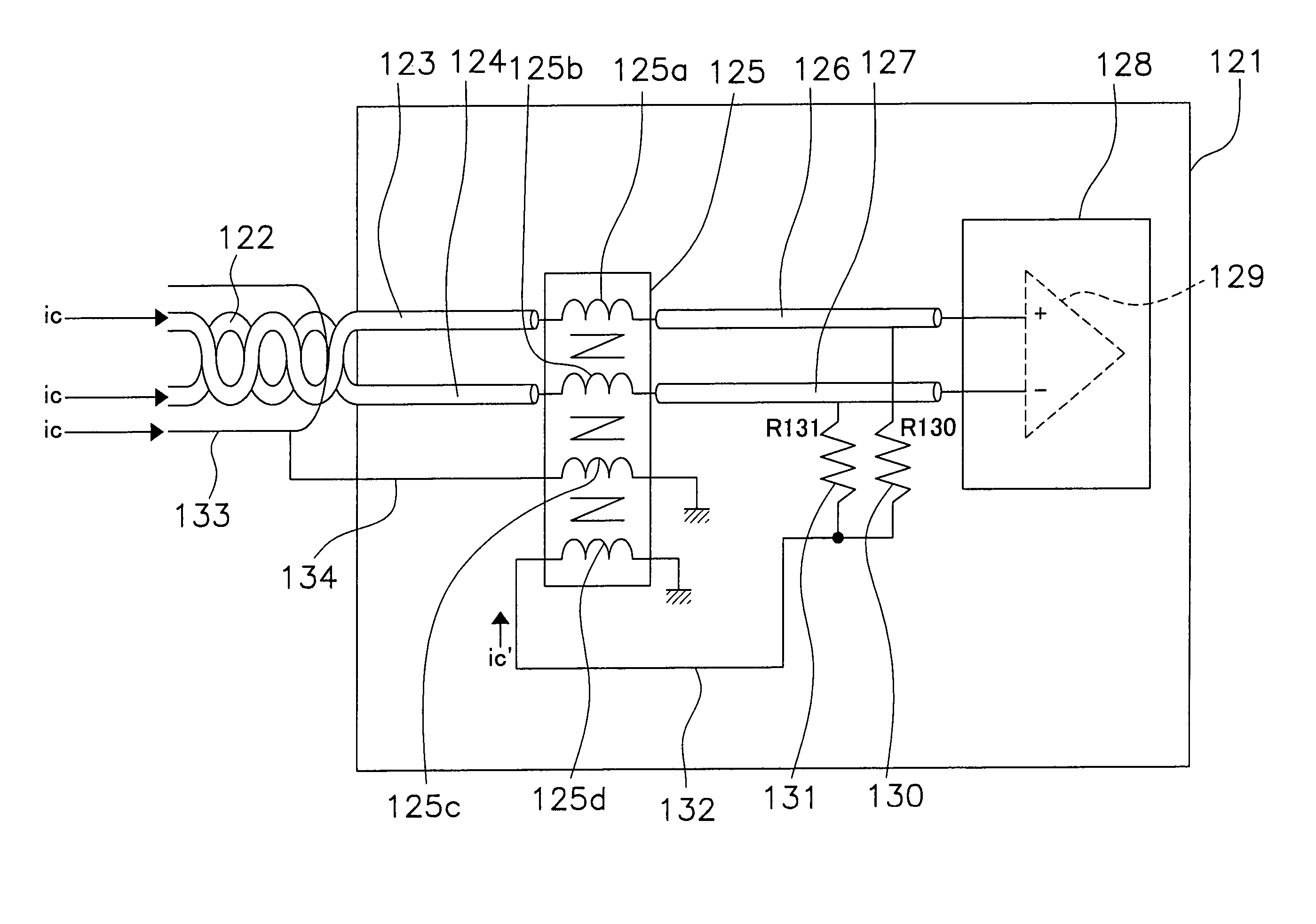
[0074]FIG. 1 is a diagram of a first embodiment of the differential transmission circuit of the present invention. This differential transmission circuit is used in devices installed in vehicles such as, for example, car navigation devices and audio devices and the like, to transmit signals between on-board devices.

[0075]The differential transmission circuit 1 of FIG. 1 includes a first transmission line 3, second transmission line 4, third transmission line 6, fourth transmission line 7, common mode choke coil 5, semiconductor device 8, first terminator 10, and second terminator 11. The first transmission line 3 and second transmission line 4 are connected to a paired transmission line in the form of a line from outside the differential transmission circuit 1, so as to connect the differential transmission circuit 1 with external electronic devices. The first transmission line 3 transmits a first signal received from an external electronic device, and the second...

second embodiment

(2) Second Embodiment

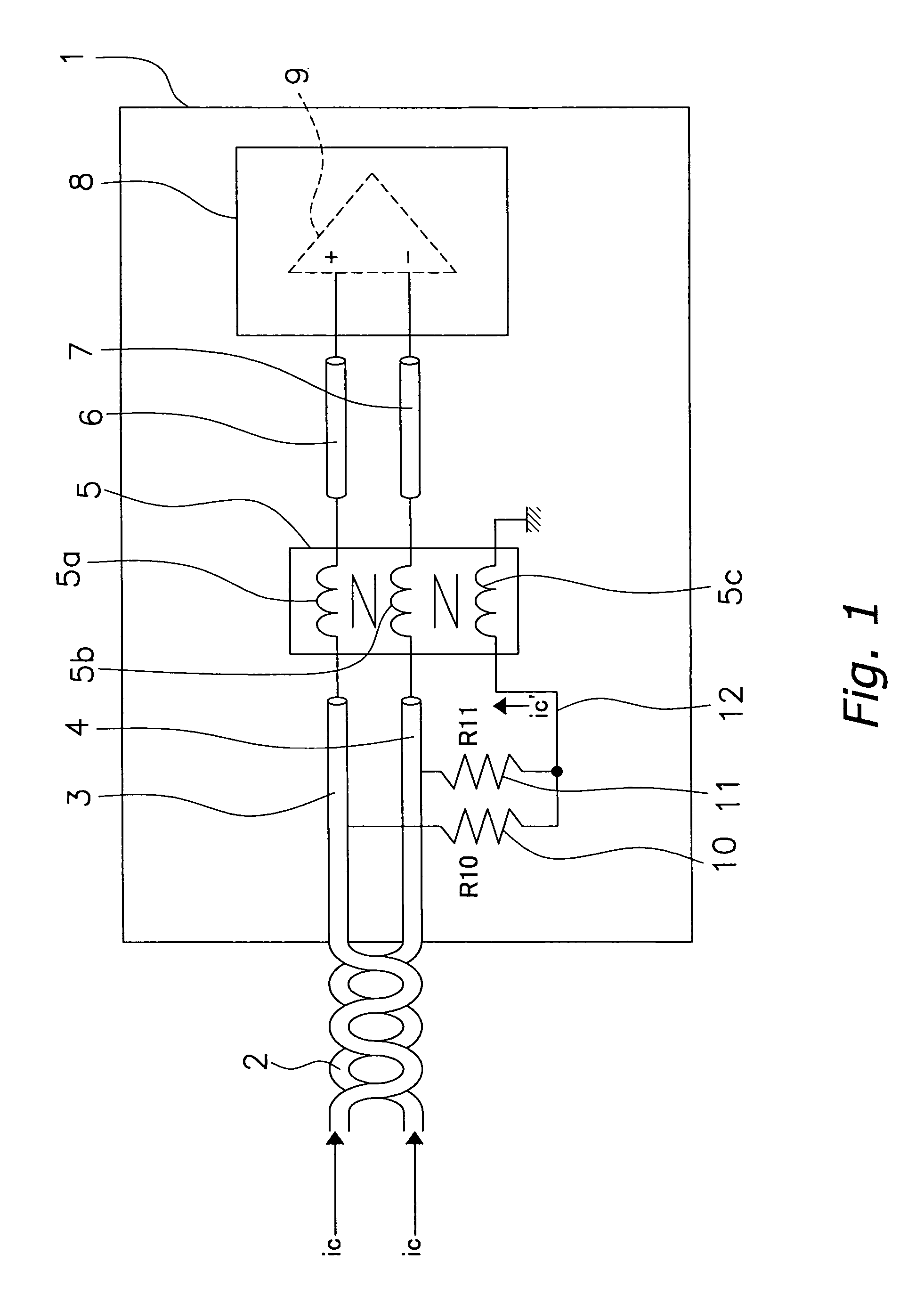
[0093]FIG. 2 is a diagram of a differential transmission circuit of a second embodiment of the present invention. The differential transmission circuit 21 of this embodiment is applicable to cases in which the length of the third and fourth transmission lines 26 and 27 is longer than the third and fourth transmission lines 6 and 7 of the first embodiment.

[0094]The differential transmission circuit 21 of FIG. 2 has one end of the first terminator 30 and second terminator 31 connected in parallel with the third transmission line 26 and fourth transmission line 27, respectively. The other end of the first terminator 30 and second terminator 31 is connected to one end of a lead 25c of the common mode choke coil 25 from the signal transmission direction side. The other end of the lead 25c is connected to a ground. In other respects the structure of the differential transmission circuit 21 is identical to that of the first embodiment. That is, a first transmission lin...

third embodiment

(3) Third Embodiment

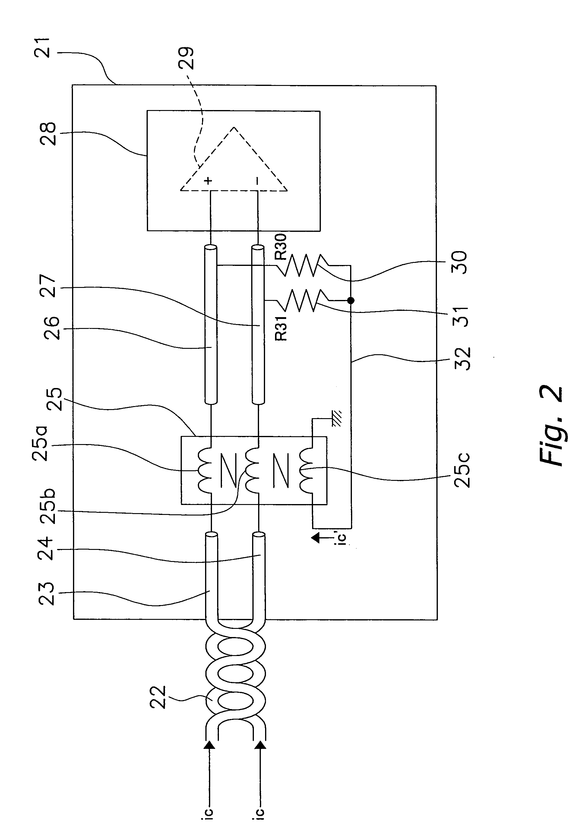
[0107]FIG. 3 is a diagram of a differential transmission circuit of a third embodiment of the present invention. The differential transmission circuit 41 of this embodiment is applicable to cases in which the length of the third and fourth transmission lines 46 and 47 is longer than the third and fourth transmission lines 6 and 7 of the first embodiment, similar to the differential transmission circuit 21 of the second embodiment.

[0108]The differential transmission circuit 41 of FIG. 3 differs in two respects from the structure of the second embodiment, as described below. First, the first and second terminators 50 and 51 are connected to one end of the lead 45c of the common mode choke coil 45 from the opposite side relative to the signal transmission direction. Secondly, the lead 45c of the common mode choke coil is wound in the opposite direction relative to the other leads a and b. The other end of the lead 45c is connected to a ground.

[0109]Other aspects of ...


PUM

PropertyMeasurementUnit
weightaaaaaaaaaa
reverse phaseaaaaaaaaaa
electric potentialaaaaaaaaaa

Abstract

A first transmission line for transmitting a first signal and a second transmission line for transmitting a second signal, which has the reverse phase of the first signal, are connected in series with a common mode choke coil. A third transmission line and fourth transmission line are each connected in series with the common mode choke coil, and transmit the first and second signals. A semiconductor device is connected in series with the third and fourth transmission lines, so as to transmit and receive the first and second signals. One end of a first terminator is connected in parallel with the first transmission line, and the other end is connected to the common mode choke coil. One end of a second terminator is connected in parallel with the second transmission line, and the other end is connected to the common mode choke coil. The noise eliminating capability of the common mode choke coil is increased by means of this structure.

Description

BACKGROUND OF THE INVENTION[0001]1. Field of the Invention[0002]The present invention relates to a differential transmission circuit and a common mode choke coil.[0003]2. Background Information[0004]In recent years there have been increasing demands for the transmission of high-frequency signals in conjunction with the diversification of electronic devices. In general, differential transmission is used for high-frequency signal transmission.[0005]In particular, when differential transmission is applied to the transmission of high-frequency signals, electromagnetic interference affecting external electronic devices can be reduced. Moreover, differential transmission can reduce the effects of electromagnetic interference from external electronic devices.[0006]Consider a case in which there is strong electromagnetic interference from external electronic devices, which affects differential transmission and causes noise to be carried in two transmission signals. When the noise carried in...

Claims


Application Information

Patent Timeline
Patent Type & Authority Patents(United States)
IPC IPC(8): H03H7/00H01F17/06H01P5/00H03H7/38H03H7/42H04B3/28H04B3/30H04L25/02
CPCH01F17/06H04L25/0272H01F2017/0093H01F2017/067
Inventor SUENAGA, HIROSHISHIBATA, OSAMUSAITO, YOSHIYUKI
Owner PANASONIC CORP
Why Eureka
Try Eureka