
Dynamic optimizing traffic planning method and system

a traffic planning and dynamic optimization technology, applied in the field of traffic planning methods, can solve problems such as device failure, known to employ a non-optimizing traffic planner, and inability to optimize the movemen

Active Publication Date: 2008-06-10
ANSALDO STS USA INC
View PDF28 Cites 36 Cited by
  • Summary
  • Abstract
  • Description
  • Claims
  • Application Information

AI Technical Summary

Problems solved by technology

Several railroads are known to employ a non-optimizing traffic planner, which does not have the capacity to optimize the movements of trains across a rail network.
Since it is relatively very expensive to lay new rail, which is one way to increase service capabilities, the railroads are looking for ways to utilize more of the capacity of their existing rail infrastructure.
That is, events did not take place in the field as planned (e.g., trains may have moved more slowly than planned; a speed limit may have been imposed on a particular segment of track; a device failure may have occurred).
This dynamic planning method can be costly from the standpoint of time, since generating an initial plan can take considerably more time than modifying the currently executing plan, depending on the optimization methods employed.
The second type of dynamic planning employs local optimization, which may adversely affect the globally optimized movement plan; that is, the degree of optimization of the overall plan as measured against the objectives is likely to be less.
In most cases, local optimization does not improve the overall global optimization of a plan.
This repairs problems when they arise, independent of the effects those repairs (i.e., new meet points) might have on causing train conflicts further out in time.

Method used


Image

  • Dynamic optimizing traffic planning method and system
  • Dynamic optimizing traffic planning method and system
  • Dynamic optimizing traffic planning method and system

Examples


example 1

[0051]The generation of movement plans observes various limitations (e.g., track speed limits; permanent speed limits; temporary speed limits) and constraints (e.g., train type, such as passenger versus freight; power type: diesel, AC, DC; train height, length, weight, width and other consist characteristics, such as, for example, dangerous goods). Also, movement plan generation observes intrinsic characteristics of the railroad devices and wayside equipment (e.g., switches and interchanges) that may further limit the generation of the movement plan. For example, the usage of a track section prohibits the usage of another track section that may or may not be connected. As another example, a track section that includes a switch in the normal position prevents the use of another track section that includes the same switch in the reverse position for a certain period of time that depends on the use of the former track section. A combination of switches in an interchange limits the use ...

example 2

[0066]For example, as shown in FIG. 9, various trains, such as train 24 (only one is shown), already occupy the track sections 26,28 of the reservations 30,32 under execution. The committed reservations 34,36,38 include reservations already allocated by the DOTP 2. Such committed reservations are not reversed by the DOTP 2; however, manual intervention may reverse them, assuming that it is safe to perform that operation. The trains are expected to move in the very near future according to these reservations and have been given “authority” to do so. In general, this means, for example, that signal lamps feature aspects that allow movement of the trains over the track sections 40,42,44 controlled by them. When trains are expected to continuously move, multiple reservations for each train may be included within this deep planning boundary 45. A train stop (e.g., at a station or because of traffic conditions) may cause a reduced number (e.g., down to zero) of committed reservations (and...

example 3

[0075]An example of an objective function is shown in Equation 5. The objective is to minimize the weighted lateness according to a global business objective function modeled discretely using evaluation points.

[0076]f=∑j=1m⁢∑i=1nj⁢wij⁢fc⁡(τij)(Eq.⁢5)

wherein:[0077]wij=f(date,time,direction) for each train service, with the function, f, being determined from the business objective (e.g., predetermined and presented to the planner in a configuration table);[0078]τij=(−1)(scheduled time−actual time for evaluation point i of train j);[0079]nj is the number of evaluation points (EPs) for train j, with each EP being a scheduled point (SP) in a relatively simple implementation. In other words, not all SPs have to be EPs: {∪injEPi}⊂{∪ikjSPj}. In a more sophisticated implementation, the EPs are not SPs, but are derived from them;[0080]kj is number of scheduled points;[0081]m is number of train services, each of which is scheduled for a physical train; and[0082]fc is a local cost function depe...


PUM


Abstract

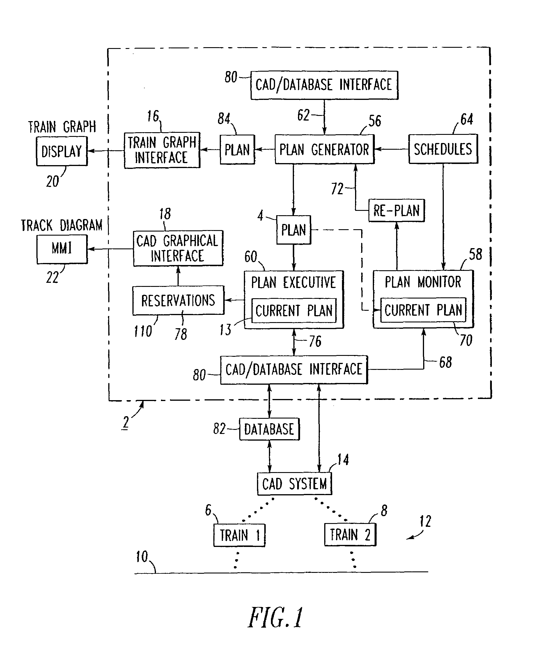
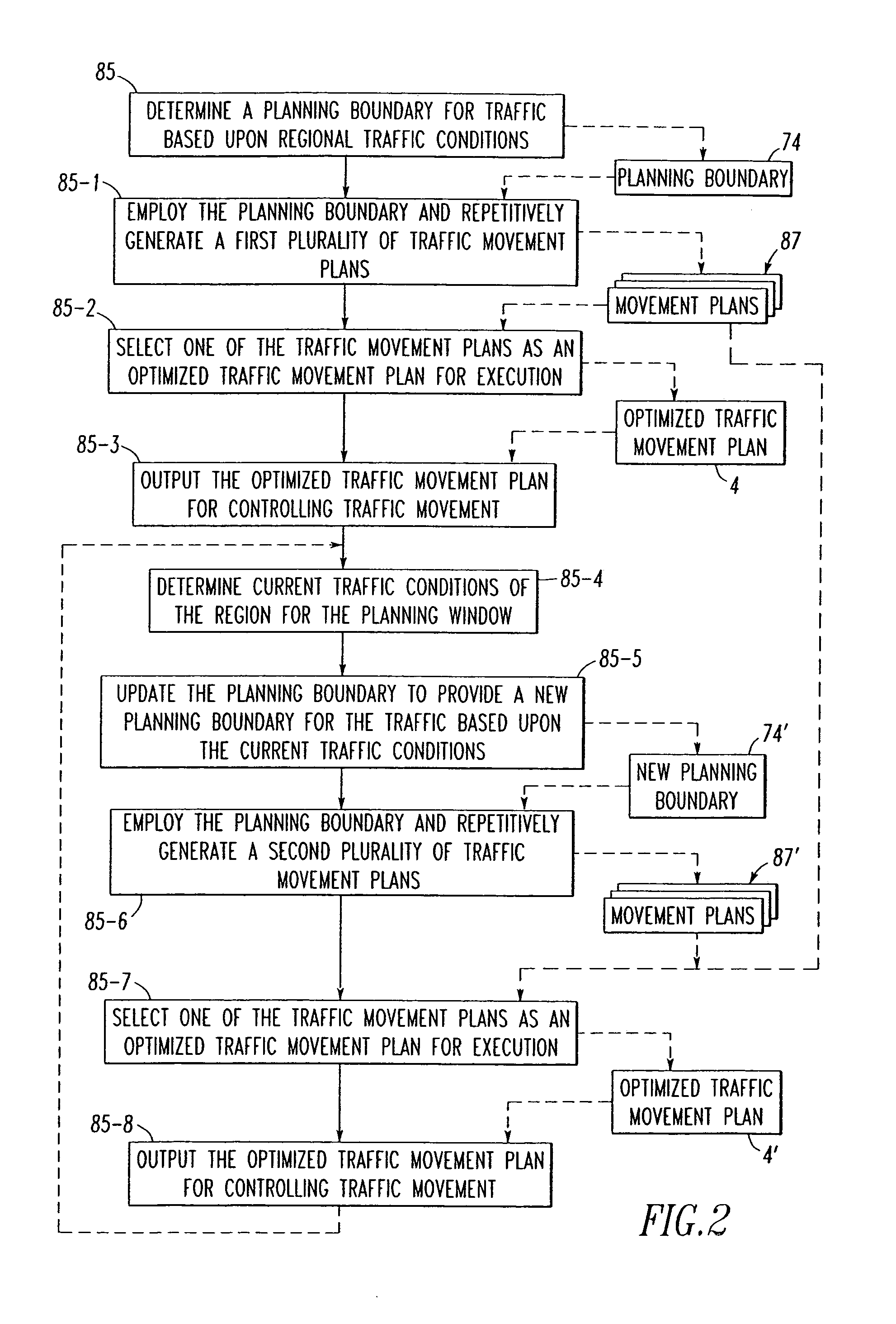
A method generates optimized traffic movement plans. A plan monitor determines a first planning boundary for traffic based upon traffic conditions of a region. A plan generator employs the first planning boundary and repetitively generates first traffic movement plans for the traffic. The plan generator selects one of the first traffic movement plans as a first optimized traffic movement plan, and outputs the same for controlling traffic movement. The plan monitor determines current traffic conditions of the region for a planning window, and updates the first planning boundary to provide a second planning boundary for the traffic based upon the current traffic conditions. The plan generator employs the second planning boundary and repetitively generates second traffic movement plans for the traffic, selects one of the first and second traffic movement plans as a second optimized traffic movement plan, and outputs the same for controlling traffic movement.

Description

CROSS-REFERENCE TO RELATED APPLICATION[0001]This application claims the benefit commonly assigned U.S. Provisional Patent Application Ser. No. 60 / 435,114, filed Dec. 20, 2002, entitled “Dynamic Optimizing Traffic Planner Method and System”.BACKGROUND OF THE INVENTION[0002]1. Field of the Invention[0003]This invention relates generally to a method for traffic planning and, more particularly, to a method for generating and dynamically modifying optimized traffic movement plans. The invention also relates to a dynamic optimizing traffic planning system, such as a railroad or commuter rail dynamic optimizing traffic planning system.[0004]2. Background Information[0005]A transportation infrastructure consists of a plurality of physical pathways (e.g., without limitation, roads; rails; canals) for vehicles (e.g., without limitation, trucks; trains; ships or boats) within a particular geographic region. Traffic planning is the process of determining, for a particular transportation infrast...

Claims


Application Information

Patent Timeline
Patent Type & Authority Patents(United States)
IPC IPC(8): G08G1/00B61L27/00G06Q10/04G06Q10/00
CPCB61L27/0027G06Q10/047G08G1/0104B61L2205/04B61L27/12B61L27/16G06Q10/04G06Q50/30
Inventor MORARIU, VIORELBOYLE, C. FRANKLINDEUTERMANN, UWEBARRY, GREGORY P.KORYTKO, ANDREY A.
Owner ANSALDO STS USA INC
Learn More