Liquid container, component for forming liquid container, and method for producing liquid container

Inactive Publication Date: 2008-06-17
SEIKO EPSON CORP
View PDF30 Cites 2 Cited by
  • Summary
  • Abstract
  • Description
  • Claims
  • Application Information

AI Technical Summary

Benefits of technology

[0055]Thus, according to the present invention, since liquid is injected into the inside of the liquid containing portion of the liquid container through the recess portion for accommodating the valve body, injection of liquid to the liquid container is not hindered by the check valve. Further, since the recess portion for accommodating the valve body is sealingly closed by the first flexible component after the injection of the liquid, the liquid container, i.e. a completed product, has the check valve having a function of allowing the flow of liquid only from the inside of the liquid containing portion to the outside.
[0056]Namely, even if the liquid container comprises the check valve, provided in the liquid flow path, for stopping the flo

Problems solved by technology

In the case where the valve body accommodating chamber is formed by crimping rigid bodies together, for example, dimensional deviatio

Method used


Image

  • Liquid container, component for forming liquid container, and method for producing liquid container
  • Liquid container, component for forming liquid container, and method for producing liquid container
  • Liquid container, component for forming liquid container, and method for producing liquid container

Examples


embodiment 1

[0089]The following description will describe one embodiment to give a concrete form to the invention with reference to FIG. 1 to FIG. 11.

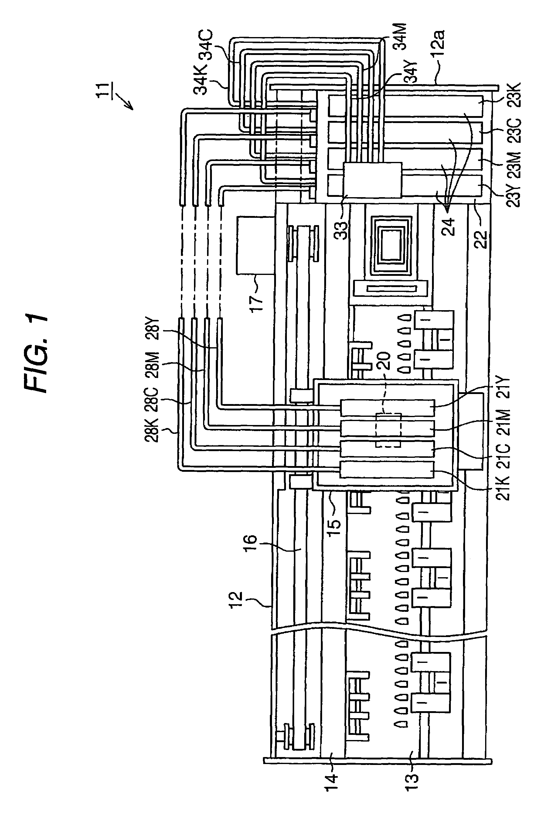
[0090]As shown in FIG. 1, a printer 11 as an ink jet recording apparatus according to the present invention comprises a nearly rectangular parallelepiped frame 12 with an opening on its upper side. A paper-feeding component 13 is constructed on the frame 12 so that a paper can be fed on this paper-feeding component 13 by a paper-feeding mechanism (not shown). A guide component 14 is constructed on the frame 12 in parallel to the paper-feeding component 13. In this guide component, the carriage 15 is inserted and supported movably in the axis direction of the guide component 14. In addition, this carriage 15 is connected to a carriage motor 17 via a timing belt 16. The carriage motor 17 drives the carriage 15 so as to move along the guide component 14 back and forth.

[0091]A recording head 20 is mounted on the surface of the carriage 15 opposing the...

embodiment 2

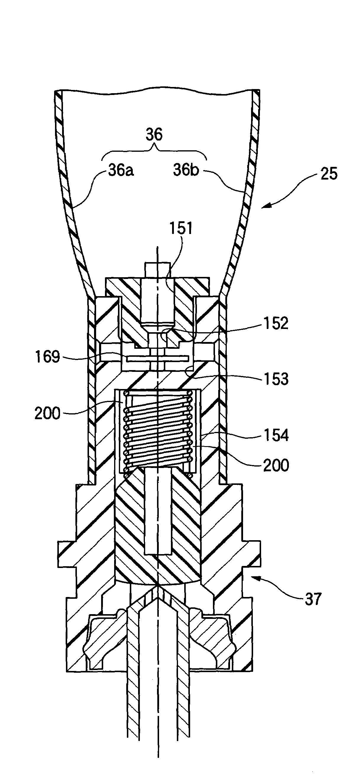
[0150]The following description will describe an Embodiment 2 to give a concrete form to the invention with reference to FIG. 13 to FIG. 15. In addition, in Embodiment 2, only a construction corresponding to the outlet portion 37 of the ink pack 25 according to Embodiment 1 is different from Embodiment 1, therefore, description of components the same as or similar to those of Embodiment 1 is omitted.

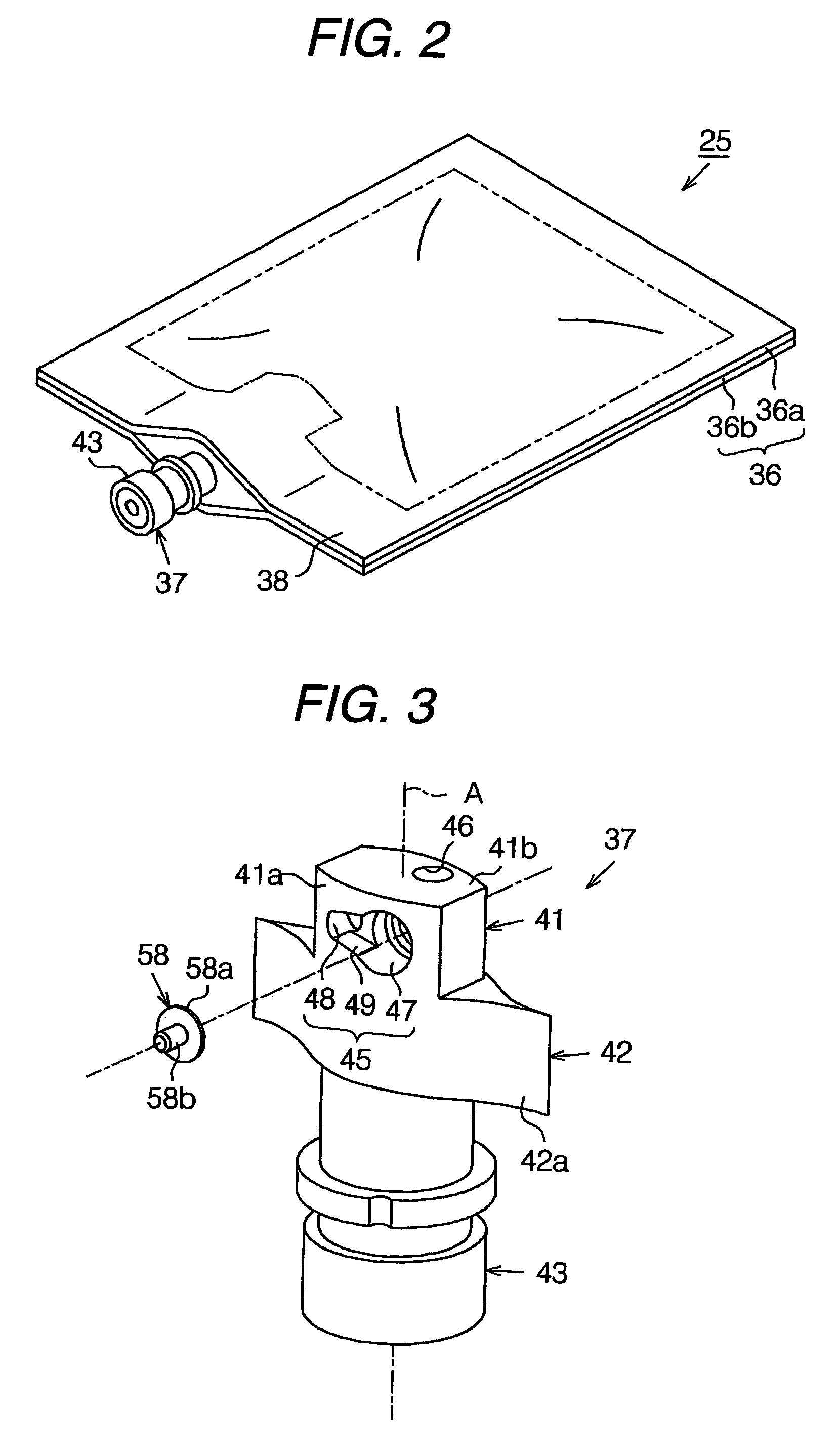
[0151]As shown in FIG. 13, an outlet portion 103 according to this embodiment comprises a first flow path forming component 104, a second flow path forming component 42, and a third flow path forming component 43. Regarding the second and third flow path forming components 42 and 43, their constructions are similar to those of Embodiment 1, and description is omitted.

[0152]The first flow path forming component 104 has a large recess portion 105 which is recessed from one side surface 104a in the direction perpendicular to the axis line A. The large recess portion 105 includes a first rec...

embodiment 3

[0160]The following description will describe an Embodiment 3 to give a concrete form to the invention with reference to FIG. 16 and FIG. 17. In addition, in Embodiment 3, only a construction corresponding to the ink pack 25 according to Embodiment 1 is different from Embodiment 1, therefore, description of components the same as or similar to those of Embodiment 1 is omitted.

[0161]As shown in FIG. 16, an ink pack 121 as a liquid container according to this embodiment comprises a box body 122 with an opening in the topside as a component for forming liquid containing portion, and a film member 123, which sealingly closes the opening in the top side of the box body 122, as a third flexible member. The inside of the box body 122 is divided into two areas by a dividing board 122a. Accordingly, the box body 122 has a first space 124, and a second space 125 that serves as a recess portion for containing liquid.

[0162]The first space 124 is formed with a cylinder body 126 extending across ...


PUM


Abstract

The present invention provides a liquid container which has a check valve for preventing a flow of outside air into its inside and which is capable of maintaining the performance of the check valve constant. An ink pack (25) includes a bag portion (36), which holds an outlet portion by heat-welding. An internal space (S) is formed in the bag portion (36), and ink is contained therein. The outlet portion has a first flow path forming component (41). A first recess portion (47) is recessed from the one side surface (41a) of the first flow path forming component (41). First and second ink flow paths (46, 51), which communicate with the internal space (S), extend from a bottom surface (47a) of this first recess portion (47). A valve seat (53) is formed in a projecting shape so as to surround the second ink flow path (51). A laminate film (36a) sealingly closes the first recess portion (47). Thus, a valve body accommodating chamber (55) is formed. The valve body accommodating chamber (55) accommodates a first valve body (58). The valve body (58) and the valve seat (53) form a first valve device (59).

Description

BACKGROUND OF THE INVENTION[0001]The present invention relates to a liquid container, a component for forming a liquid container, and a method for producing a liquid container.[0002]Conventionally, an ink jet recording apparatus has been widely used as a liquid ejecting apparatus, which ejects liquid to a target. In greater detail, this ink jet recording apparatus comprises a carriage, a recording head mounted on the carriage, and an ink cartridge containing ink as liquid. Printing is carried out on a recording medium by ejecting ink from nozzles formed on the recording head while moving the carriage relative to the recording medium and providing ink to the recording head from the ink cartridge.[0003]Moreover, in such an ink jet recording apparatus, in order to reduce the load on a carriage, or to make the apparatus compact and thin, there is a structure, in which an ink cartridge is not mounted on a carriage (a so-called off-carriage type). Such an ink cartridge typically includes ...

Claims


Application Information

Patent Timeline
IPC IPC(8): B41J2/175
CPCB41J2/17513B41J2/17553B41J2/17556B41J2/17559B41J2/17596
Inventor KIMURA, HITOTOSHIISHIZAWA, TAKU
Owner SEIKO EPSON CORP
Why Eureka
Try Eureka