
Secure fiber optic connector and adapter systems

a technology of fiber optic connectors and adapters, applied in the field of physical barriers, can solve problems such as secure connectors, and achieve the effect of facilitating users in correct and quick identification

Active Publication Date: 2008-06-17
CORNING OPTICAL COMM LLC
View PDF14 Cites 141 Cited by
  • Summary
  • Abstract
  • Description
  • Claims
  • Application Information

AI Technical Summary

Benefits of technology

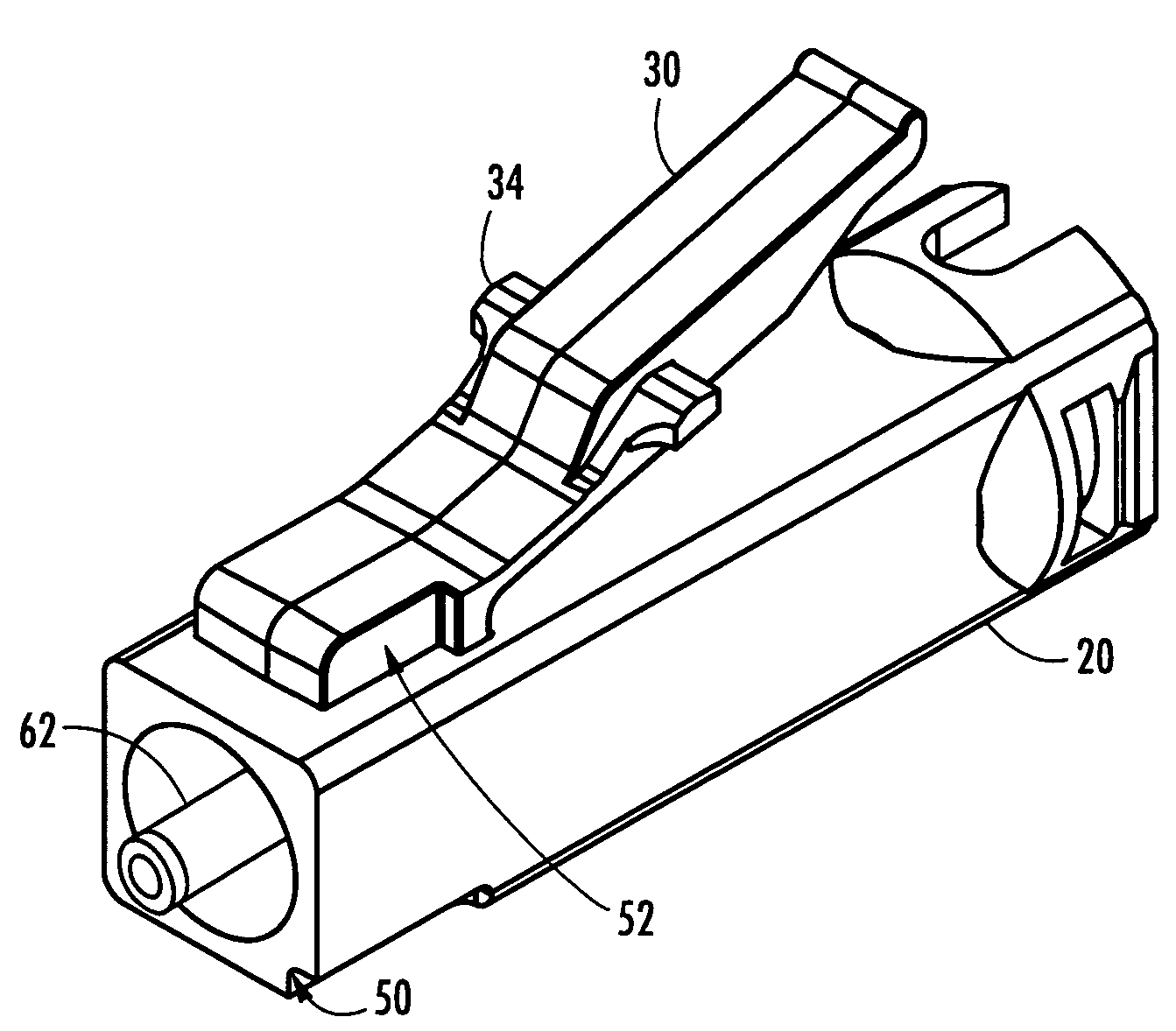
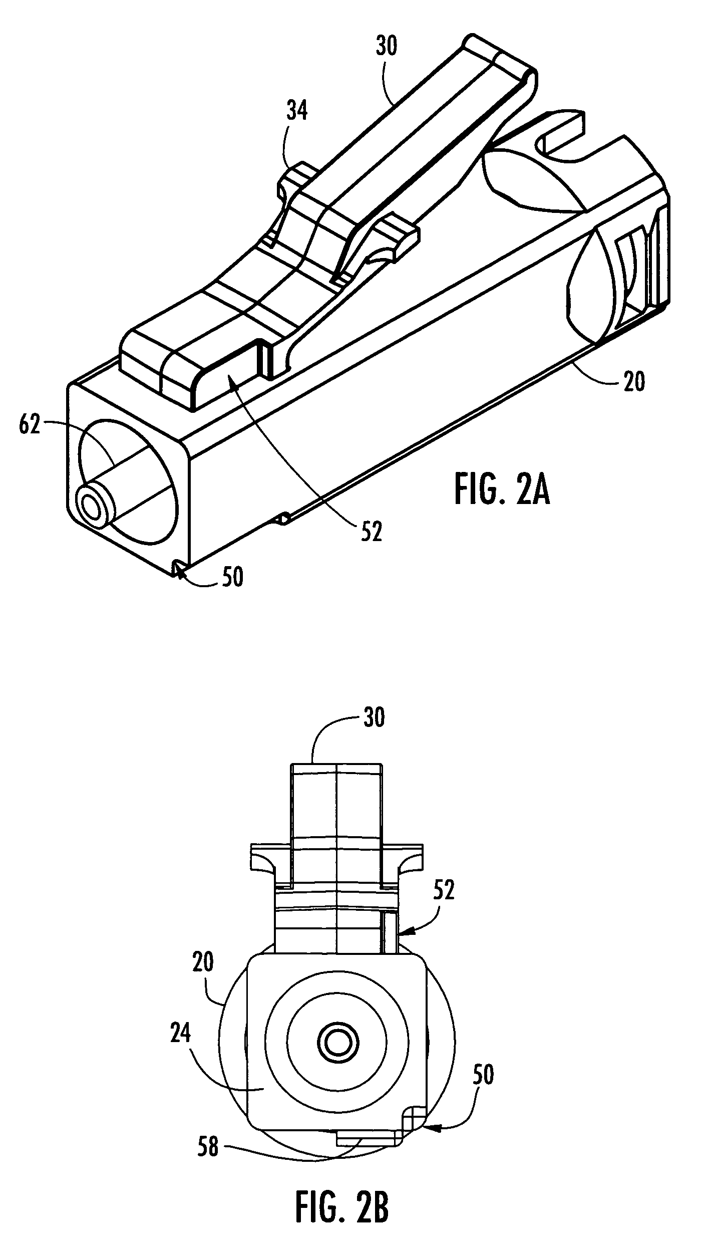
The present invention provides fiber optic connectors and adapters with matching physical security features to restrict optical connection access in a fiber optic network. The physical security features allow a connector to mate with an adapter including the matching security structure, while preventing non-matching connectors from mating. The connectors have a first key slot and a second key slot, which provide eight different matched keying combinations. The second key slot may be defined by a portion of the latch that is activated to secure the connector within an adapter and withdraw the connector from the adapter. The secure LC fiber optic connector and adapter system for use within a fiber optic network includes a connector housing and a ferrule assembly positioned and maintained within one end of the opening of the connector housing. The connector housing has a first key slot recessed within a predetermined portion of the outer surface of the housing about the connective end of the connector. The keys in the adapter prevent a connector that does not have matching key slots from latching into the adapter or transmitting information. The secure connector and adapter families include a first key slot defined by the connector main body, which can be relocated to each of the four corners of the connector main body to create four secure connector families. The main body of the connector also has a second key slot that prevents connectors without the slot from latching into the adapter or transmitting information. The connector and adapter may have matching colors or be otherwise marked for visual identification.

Problems solved by technology

Additionally, a rib on the bottom of all of the connectors prevents secure connectors from being latched into a non-secure adapter.

Method used


Image

  • Secure fiber optic connector and adapter systems
  • Secure fiber optic connector and adapter systems
  • Secure fiber optic connector and adapter systems

Examples


Embodiment Construction

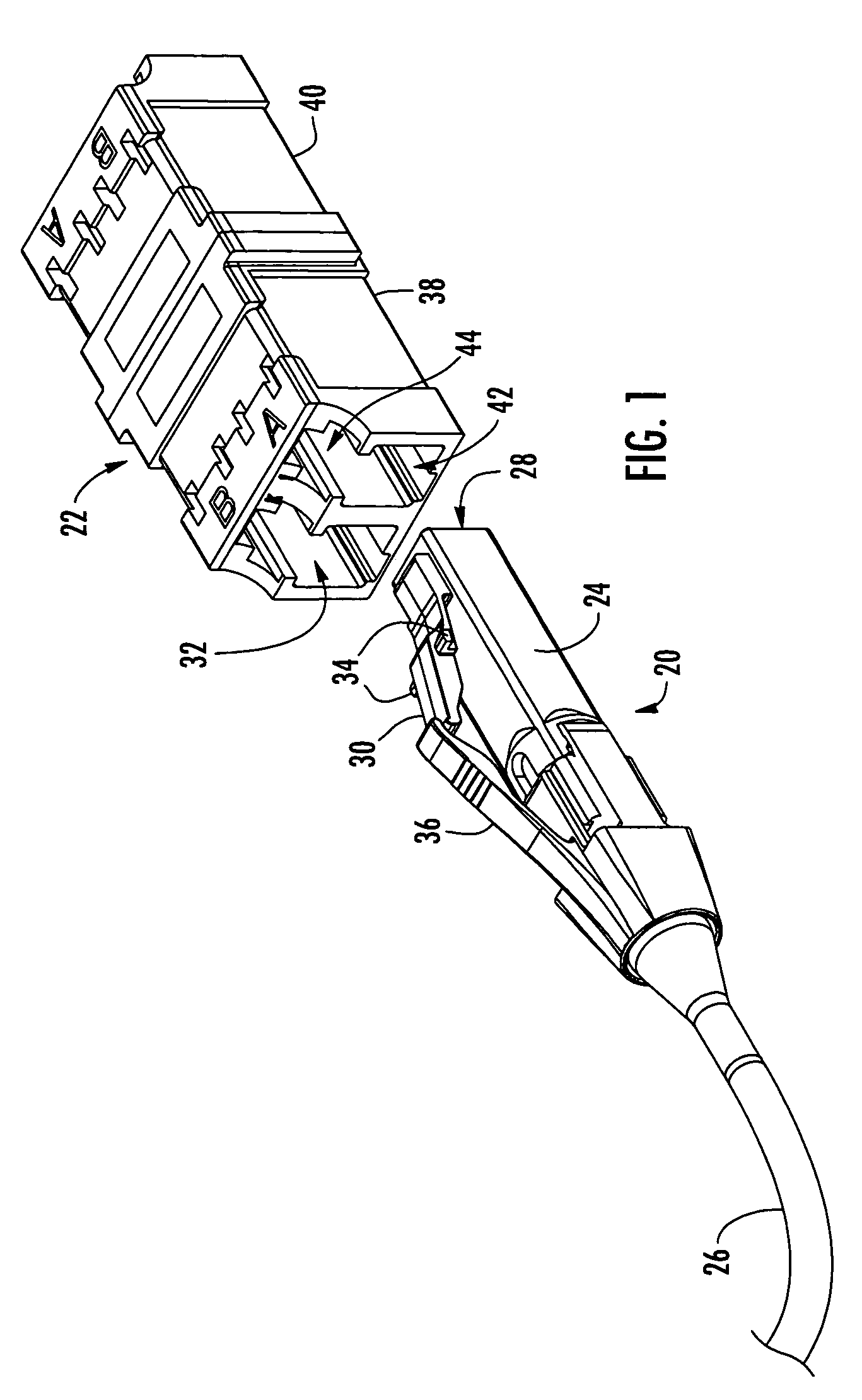
[0021]Reference will now be made in detail to the preferred embodiments of the present invention, examples of which are illustrated in the accompanying drawings. Whenever possible, like reference numbers will be used to refer to like components or parts. While specific embodiments of geometries for physical security for fiber optic connectors is shown, it is envisioned that alternative geometries and security feature positions may be used to perform similar functions. In addition, while secure LC connectors and corresponding adapters are shown throughout the various figures, it is envisioned that the concepts and geometries may be applied to any fiber optic connector including, but not limited to, LC, SC, FC, MT-RJ, MT and like connectors.

[0022]Referring now to FIG. 1, an LC connector 20 and corresponding adapter 22 are shown. The connector 20 defines at least a first key slot and a second key slot that are engaged by a first key and a second key of the adapter 22, respectively. The...


PUM


Abstract

A secure fiber optic connector and adapter system including at least one connector including a first housing portion defining a first key slot and a second housing portion defining a second key slot independent of the first key slot, and at least one adapter including a first cavity for receiving the first housing portion and defining a first key therein for engaging with the first key slot, and a second cavity for receiving the second housing portion and defining a second key therein for engaging with the second key slot, wherein only a connector and an adapter having corresponding key slots and keys may mate. A secure fiber optic connector and adapter system for providing a level of secure access within a fiber optic network.

Description

BACKGROUND OF THE INVENTION[0001]1. Field of the Invention[0002]The present invention relates generally to physical barriers for restricting access within secure fiber optic networks, and more specifically, to fiber optic connectors and associated adapters that include corresponding physical security features for restricting access to optical connections within a fiber optic network.[0003]2. Technical Background of the Invention[0004]Fiber optic networks have been developed that include numerous optical connection points at which optical fibers are interconnected. It is often common within organizations with large information networks to create multiple security levels to prevent sensitive information from being accessed by unauthorized users. Typically, these networks include fiber optic connectors that physically cannot be connected to an incorrect security level, thereby preventing unauthorized users from accessing sensitive information.[0005]One example of a connector for secure...

Claims


Application Information

Patent Timeline
Patent Type & Authority Patents(United States)
IPC IPC(8): G02B6/38G02B6/36
CPCG02B6/3825G02B6/3831G02B6/3893
Inventor MUDD, RONALD L.RAKER, JOSHUA D.
Owner CORNING OPTICAL COMM LLC
Learn More