Active flow modifications on wind turbine blades

a technology of active flow and wind turbine blades, which is applied in the direction of liquid fuel engines, vessel construction, marine propulsion, etc., can solve the problems of large torque, which is the driving force imparted by the wind to the wind turbine, and the provision to stop the flow control, so as to improve the performance, reduce load, and the effect of large wind turbine blades

a technology of active flow and wind turbine blades, which is applied in the direction of liquid fuel engines, vessel construction, marine propulsion, etc., can solve the problems of large torque, which is the driving force imparted by the wind to the wind turbine, and the provision to stop the flow control, so as to improve the performance, reduce load, and the effect of large wind turbine blades

US7387491B2Active Publication Date: 2008-06-17LM WIND POWER US TECH APS

Image

  • Active flow modifications on wind turbine blades
  • Active flow modifications on wind turbine blades
  • Active flow modifications on wind turbine blades

Examples


Embodiment Construction

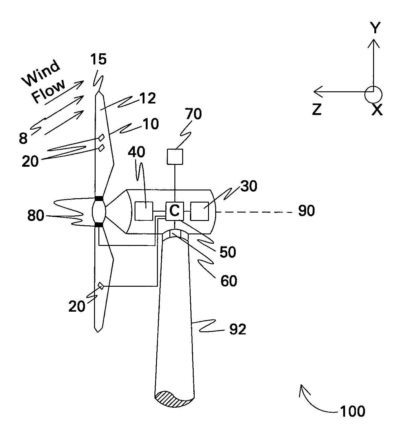
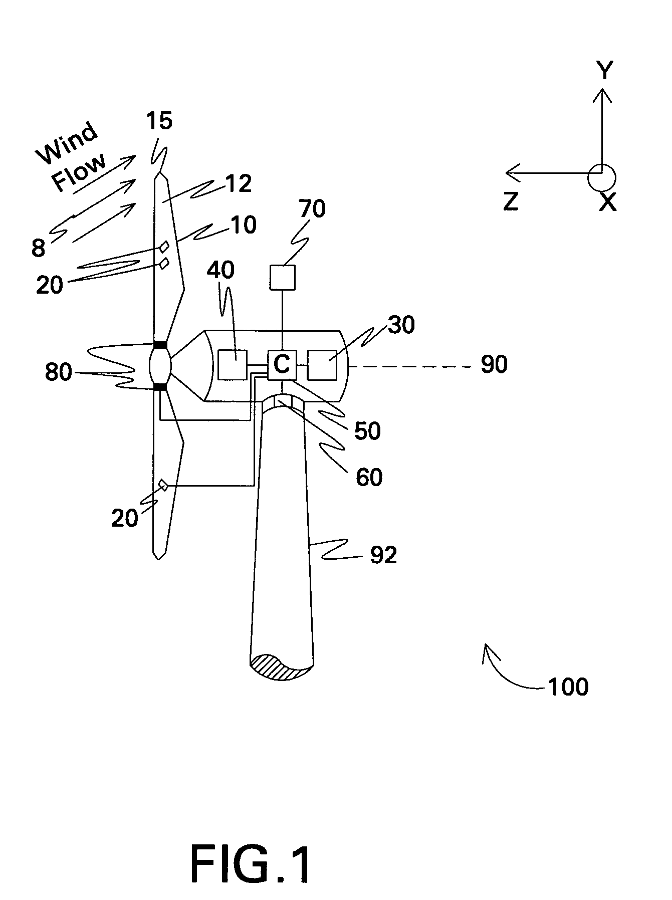
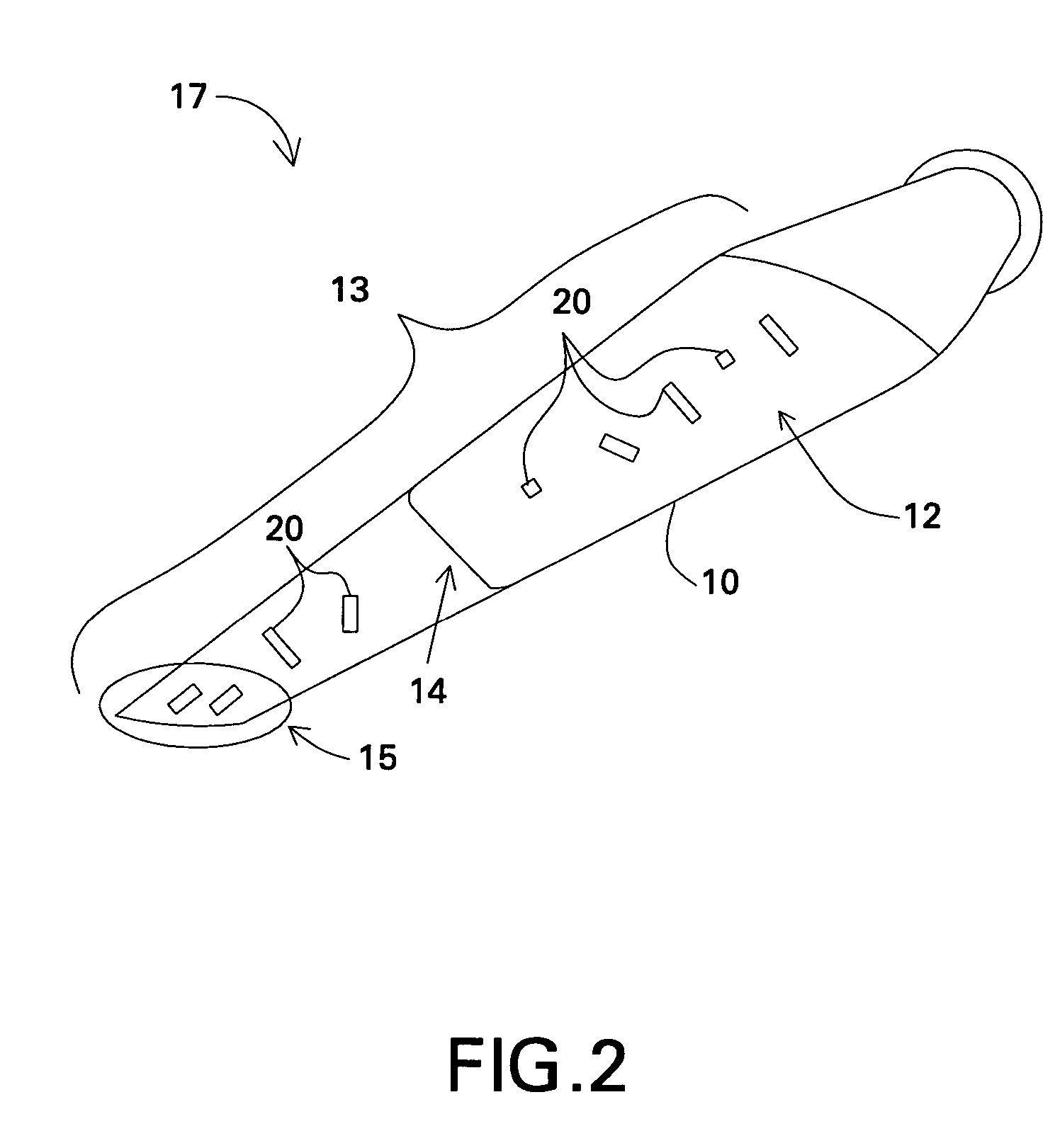
[0020]FIG. 1 illustrates a wind turbine 100 in accordance with one embodiment of the present invention. The wind turbine 100 includes a wind turbine blade 10 configured to rotate about an axis 90 upon impact of an incident wind flow, for example, a wind flow 8 as shown. It is appreciated that as used herein, the terms “a”, “an” and “the” refer to “at least one” and plural variants thereof, unless otherwise specifically mentioned or indicated by the context. The axis of rotation 90 is along the z-axis in the axes system of FIG. 1, and the plane of rotation of the blades 10 is x-y plane, the x-axis coming out of the plane of the paper. An active flow modification device 20 is further disposed on the blade 10, and the blade and the active flow modification device 20 together form a wind turbine blade assembly 17 (shown in FIG. 2). The active flow modification device 20 is configured to modify the wind flow 8 proximate to the blade, thereby modifying a load on the wind turbine. The term...


PUM


Abstract

A wind turbine blade is situated on a wind turbine and includes a side and a tip. The blade is configured to rotate about an axis upon an impact of a wind flow on the blade. An active flow modification device is disposed on the blade. The active flow modification device is configured to receive active flow instructions and to modify the wind flow proximate to the blade. The resulting wind turbine blade uses these active flow modifications to achieve reduced loads, reduced aerodynamic losses, reduced noise, enhanced energy capture, or combinations thereof.

Description

BACKGROUND[0001]The invention relates generally to the field of wind turbines, and more specifically to active flow modification in wind turbines for reducing loads, reducing aerodynamic losses, improving energy capture, reducing noise, and combinations thereof.[0002]Wind turbines are increasingly gaining importance in the area of renewable sources of energy generation. In recent times, wind turbine technology has been applied to large-scale power generation applications. Of the many challenges that exist in harnessing wind energy, one is maximizing wind turbine performance while minimizing system loads in given wind conditions. Non-limiting examples of improved wind turbine performance parameters, which lead to minimized cost of energy, include maximized aerodynamic efficiency, maximized energy output, minimized wind turbine system loads, minimized noise, and combinations thereof. Examples of wind turbine system loads include extreme loads (operational and parked / idling) and fatigu...

Claims


Application Information

Patent Timeline
17 Jun 2008
Publication
US7387491B2
IPC
F03D7/06
CPC
F03D1/0608; F05B2240/31; Y10S415/914; Y02E10/72
Inventors
SADDOUGHI, SEYED GHOLAMALI; GUPTA, ANURAG