Control system for permanent magnet synchronous motor and module

a technology of synchronous motor and control system, which is applied in the direction of motor/generator/converter stopper, dynamo-electric gear control, dynamo-electric converter control, etc., can solve the problems of uncontrollable optimal phase and apparatus falling into unoperable state, and achieve high-precision position sensor-less vector control

Active Publication Date: 2008-06-17
HITACHI POWER SEMICON DEVICE
View PDF8 Cites 9 Cited by
  • Summary
  • Abstract
  • Description
  • Claims
  • Application Information

AI Technical Summary

Problems solved by technology

When a setting error (R−R*) is caused between the set value R* and the resistance R of the motor, if an impact load disturbance is caused in the low-speed rotation area, the actual phase error value Δθ and the inference phase error value Δθc are shifted from each other, thus the optimal phase cannot be controlled, and the apparatus may fall into an un-operable state.

Method used


Image

  • Control system for permanent magnet synchronous motor and module
  • Control system for permanent magnet synchronous motor and module
  • Control system for permanent magnet synchronous motor and module

Examples


first embodiment

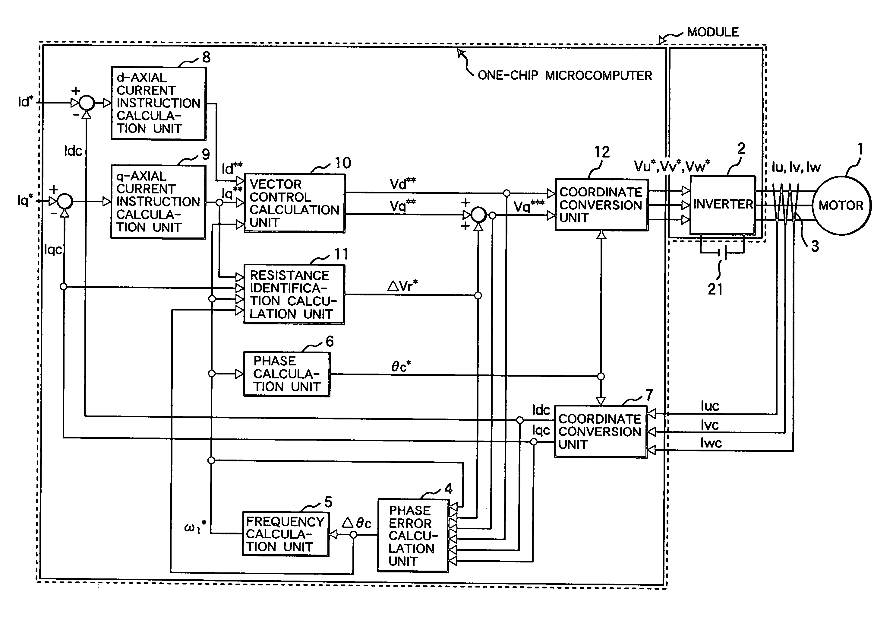
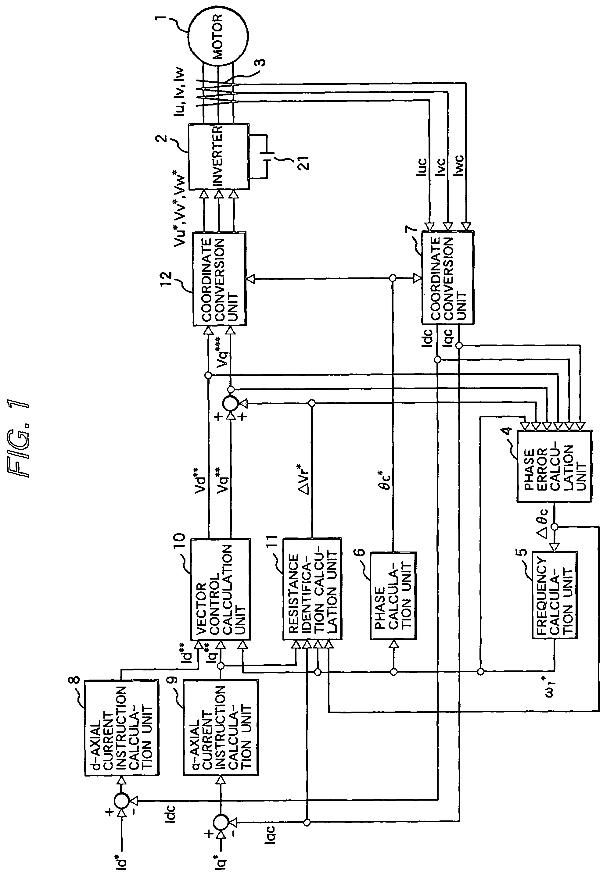
[0024]FIG. 1 shows a constitution example of the vector control system for the permanent magnet synchronous motor of an embodiment of the present invention.

[0025]Numeral 1 indicates a permanent magnet synchronous motor, 2 an inverter for outputting voltages proportional to 3-phase AC voltage instruction values Vu*, Vv*, and Vw*, 21 a DC power source, 3 a current detector for detecting 3-phase AC currents Iu, Iv, and Iw, 4 a phase error calculation unit for calculating the inference value (Δθc) of the phase error value Δθ (=θc*−θ) which is a deviation between the rotation phase instruction value θc* and the rotation phase value θ of the motor 1, 5 a frequency calculation unit for calculating the frequency instruction value ω1* from the inference phase error value Δθc, 6 a phase calculation unit for calculating the rotation phase instruction value θc* of the motor 1 from the frequency instruction value ω1*, 7 a coordinate conversion unit for outputting the d-axial and q-axial current ...

second embodiment

[0094]FIG. 6 shows another embodiment of the present invention.

[0095]This embodiment is the vector control system for the permanent magnet synchronous motor for correcting the output values Vd* and Vq* of the vector control calculation unit by the deviation between the current instruction value and the current detection value given from the host computer.

[0096]In FIG. 6, numerals 1 to 7, 12, and 21 indicate the same parts as those shown in FIG. 1.

[0097]Numeral 8a indicates a d-axial current control calculation unit for calculating ΔVd so as to make the d-axial current instruction value Id* and the d-axial current detection value Idc coincide with each other, 9a a q-axial current control calculation unit for calculating ΔVq so as to make the q-axial current instruction value Iq* and the q-axial current detection value Iqc coincide with each other, 10a a vector control calculation unit for outputting the reference values Vd* and Vq* of the voltage instruction using the d-axial and q-a...

third embodiment

[0122]FIG. 8 shows still another embodiment of the present invention.

[0123]This embodiment is the vector control system for the permanent magnet synchronous motor for directly controlling the d-axial and q-axial voltage instruction values Vd** and Vq** by the deviation between the current instruction value and the current detection value given from the host computer.

[0124]In FIG. 8, numerals 1 to 7, 12, and 21 indicate the same parts as those shown in FIG. 1. Numeral 8b indicates a d-axial current control calculation unit for controlling the d-axial voltage instruction value Vd** so as to make the d-axial current instruction value Id* and the d-axial current detection value Idc coincide with each other, 9b a q-axial current control calculation unit for controlling the q-axial voltage instruction value Vq** so as to make the q-axial current instruction value Iq* and the q-axial current detection value Iqc coincide with each other, and 11b a resistance identification calculation unit ...


PUM


Abstract

A vector control system for a permanent magnet synchronous motor, using a current control equivalent output value, a frequency instruction value, a current detection value, an inference phase error value, and a motor constant, identifies a motor resistance equivalent or a resistance setting error equivalent. Next, the vector control unit, using the identified value, corrects a set value R* equivalent of a voltage instruction calculation unit and a n inference phase error calculation unit.Thereby, a vector control system for a permanent magnet synchronous motor can realize a robust control characteristic for changing of a resistance constant of a motor in a low rotation speed area under position sensor-less control. Further, a vector control system for a permanent magnet synchronous motor can be applied in common in a system performing inexpensive current detection.

Description

CLAIM OF PRIORITY[0001]The present application claims priority from Japanese application serial no. 2004-266164, filed on Sep. 14, 2004, the content of which is hereby incorporated by reference into this application.FIELD OF THE INVENTION[0002]The present invention relates to a position sensor-less vector control system of a permanent magnet synchronous motor.BACKGROUND OF THE INVENTION[0003]As a resistance identification art of the position sensor-less vector control system, in Japanese Patent Laid-open No. 2003-164188, before starting operation of a motor, a method for applying an inverter voltage so as to restrict the motor and identifying the resistance from the voltage and restriction current flowing and during operation, a method for installing a means for identifying the counter electromotive voltage factor of the motor, inferring the motor temperature from the value identified during operation and a preset counter electromotive voltage factor at normal temperature, and ident...

Claims


Application Information

Patent Timeline
Patent Type & Authority Patents(United States)
IPC IPC(8): H02P6/08H02P6/06H02P6/182H02P6/28H02P21/00H02P21/14H02P21/16H02P21/18H02P21/22H02P21/24H02P23/14H02P27/04H02P27/08
CPCH02P21/0042H02P21/04H02P21/26
Inventor TOBARI, KAZUAKISAKAMOTO, KIYOSHIENDO, TSUNEHIROIWAJI, YOSHITAKAKAWABATA, YUKIOAOYAGI, SHIGEHISA
Owner HITACHI POWER SEMICON DEVICE
Why Eureka
Try Eureka