Methods and apparatus for porosity measurement

a composite structure and non-destructive measurement technology, applied in the direction of instruments, specific gravity measurement, counting objects on conveyors, etc., can solve the problems of early failure of critical components, different types of defects in design and manufacturing methods, and unique flaws in composite structures

Inactive Publication Date: 2008-06-24
GENERAL ELECTRIC CO
View PDF4 Cites 13 Cited by
  • Summary
  • Abstract
  • Description
  • Claims
  • Application Information

AI Technical Summary

Benefits of technology

[0014]It will be appreciated that various configurations of the present invention provide a nondestructive method for measuring the porosity content in composite structures during the manufacturing process and that this method is advantageous for designing and lifting these components. Various configurations of the present invention also measure the porosity volume in a composite structure nondestructively using readily available ultrasonic equipment. Configurations of the present invention require only one scan for ultrasonic attenuation measurement instead of multiple scans as was required for prior art techniques. Configurations of the present invention also require only one transducer, thereby simplifying calibration and inspection procedures. Method configurations of the present invention are relatively simple and straightforward requiring no unusual skills that most ultrasonic inspectors would not possess.

Problems solved by technology

New product designs and manufacturing methods can create different types of defects than those generated during the manufacture of large metal structures.
Composite structures have some unique flaws relating to the manufacturing process which do not exist with the manufacture of metallic structures.
Undetected porosity can lead to early failures of critical components.
However, acid digestion methods are destructive because the composite must be dissolved in order to measure the volume of porosity.
For most critical components for which safe operation is dependent on each component working properly, this destructive testing method cannot provide the needed level of porosity detection to assure safe operation.
To collect the ultrasonic information needed to analyze porosity would require two or more scans of the part depending on the attenuation slope calculation method used, a serious limitation to manufacturing productivity.
Another problem with the methods developed by these three groups is that the complexity of the calibration and measurements could make the inspection difficult for non laboratory-trained technicians.
These calculations would make the transfer of these techniques to a manufacturing environment very difficult.

Method used


Image

  • Methods and apparatus for porosity measurement
  • Methods and apparatus for porosity measurement
  • Methods and apparatus for porosity measurement

Examples


Embodiment Construction

[0020]Technical effects of the present invention include the non-destructive measurement of porosity of a composite structure and / or the generation of a digital imaging showing porosity of the composite structure.

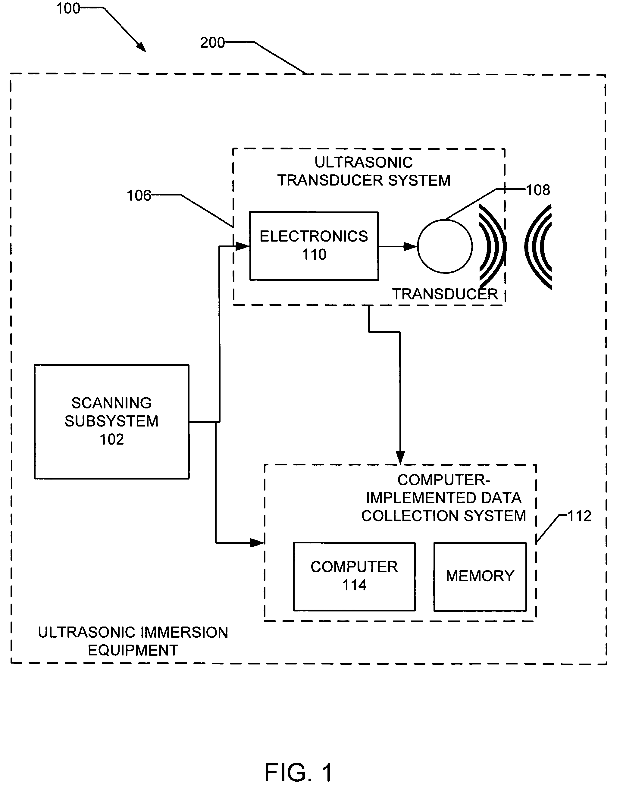
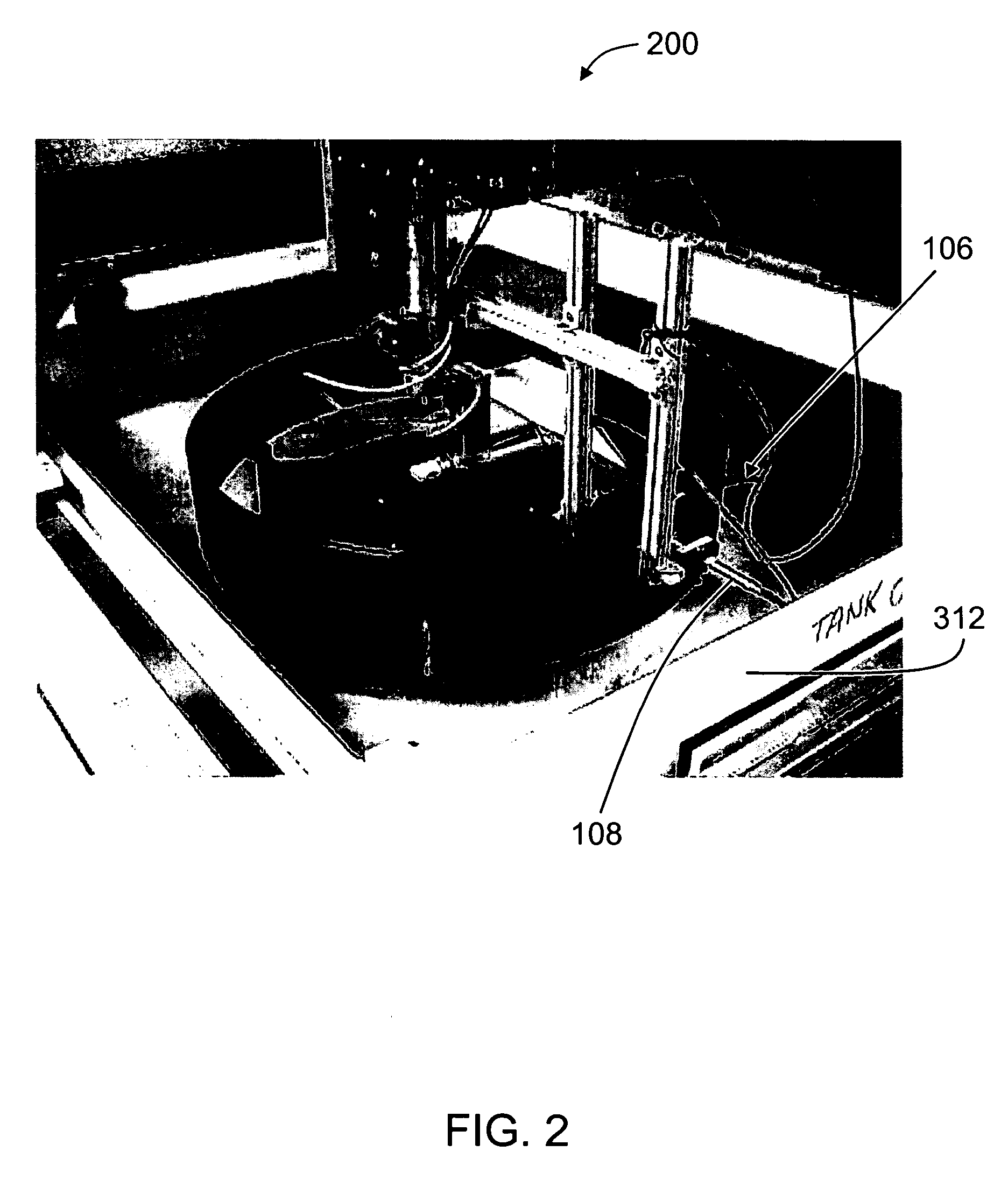
[0021]Some configurations of the present mention use a porosity measurement method that uses standard ultrasonic immersion equipment similar to equipment used for inspecting metal forgings. Such equipment is readily available for use in inspecting composite structures and is manufactured by many companies, although the computer subsystems of the readily available equipment are not preconfigured as described herein. In some configurations, and referring to the example configuration block diagram 100 of FIG. 1 and the pictorial diagram of FIG. 2, there are three subsections of ultrasonic immersion equipment 200, namely

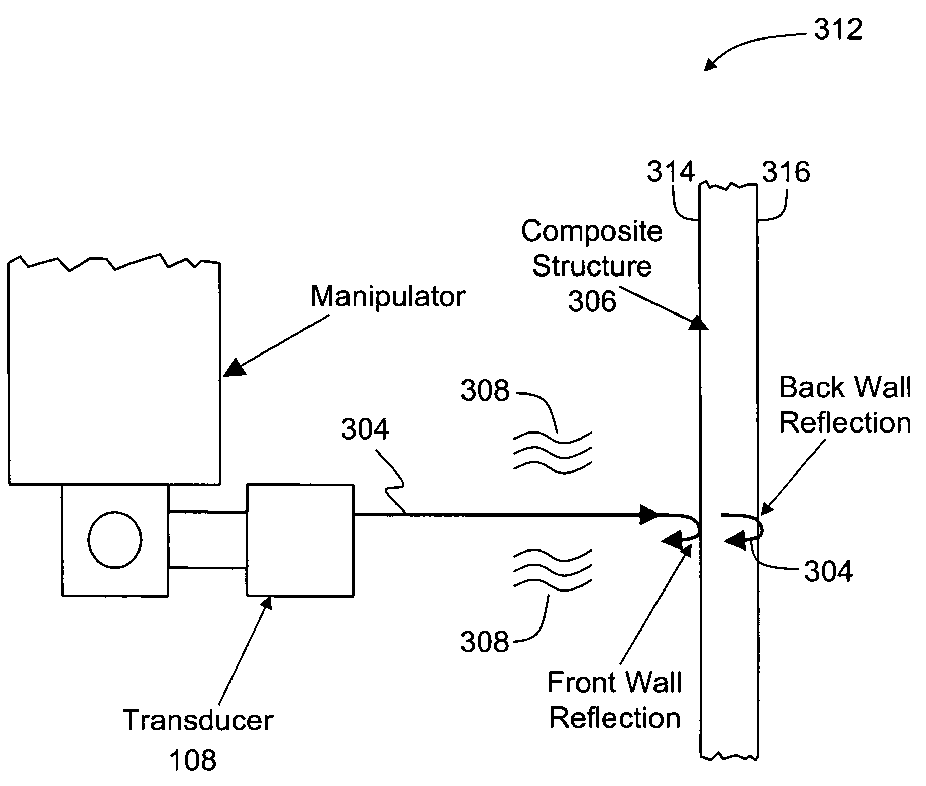
[0022](a) a scanning system 102 configured to position a transducer 108 for transmitting and collecting ultrasonic data,

[0023](b) an ultrasonic transducer syste...


PUM

PropertyMeasurementUnit
porosity×cm×MHzaaaaaaaaaa
porosityaaaaaaaaaa
porosityaaaaaaaaaa

Abstract

A method for non-destructively inspecting a composite structure with a single ultrasonic transducer includes determining a calibration amplitude of ultrasonic transmissions emitted by the single ultrasonic transducer to a reflector in a fluid-filled immersion tank and received back at the single ultrasonic transducer. The method also includes inserting the composite structure into the fluid-filled immersion tank between the reflector and the single ultrasonic transducer. In addition, the method includes scanning the composite structure with the single ultrasonic transducer to measure ultrasonic amplitudes for sound waves traveling through the composite structure, reflecting off the reflector plate and then traveling back through the structure to the single ultrasonic transducer. The measured ultrasonic amplitudes are corrected using the calibration amplitude and other measured transmission losses, and the corrected ultrasonic amplitudes are utilized to generate either or both a digital image showing porosity or a measurement of porosity of the composite structure.

Description

BACKGROUND OF THE INVENTION[0001]This invention relates generally to methods and apparatus for nondestructively measuring porosity in composite structures.[0002]The identification of internal flaws in large structures is critical to the safe use of these structures. For metal structures, the identification and characterization of melt-related inclusions and cracks are critical for lifing these parts. The inspection of large metal components led to the development of sophisticated technologies for detecting surface and volumetric defects. These technologies include x-ray, penetrant, and ultrasonic methods.[0003]New product designs and manufacturing methods can create different types of defects than those generated during the manufacture of large metal structures. The design of new structures based on polymer matrix composites is one example of these new technologies. Composite structures have some unique flaws relating to the manufacturing process which do not exist with the manufact...

Claims


Application Information

Patent Timeline
Patent Type & Authority Patents(United States)
IPC IPC(8): G01N9/00
CPCG01N15/088G01N29/06G01N29/11G01N29/30G01N29/4463G01N2015/0846G01N2291/0231G01N2291/0234G01N2291/0427G01N2291/045G01N29/22G01N29/04
Inventor REED, FRANCIS ALEXANDERBATZINGER, THOMAS JAMES
Owner GENERAL ELECTRIC CO
Why Eureka
Try Eureka