
Quick coupling having pressure relief device for multiple pressurized lines

a technology of pressure relief device and quick coupling, which is applied in the direction of couplings, water supply installations, pipe elements, etc., can solve the problems of clogging of pressure reduction elements, complex construction of pressure reduction elements located in the coupling parts, and reducing the service life of quick couplings, so as to achieve easy guidance, simple design, and safe coupling of the coupling parts in the coupled position

Inactive Publication Date: 2008-06-24
TEMA MARKETING
View PDF5 Cites 10 Cited by
  • Summary
  • Abstract
  • Description
  • Claims
  • Application Information

AI Technical Summary

Benefits of technology

[0011]According to the invention this object is met by a quick coupling for connecting at least two pressurized lines to a first coupling part that is connectable to a second coupling part so as to be pressure-proof. By providing a central pressure relief device which is integrated in a second coupling part or externally arranged in an additional block on the second coupling part, wherein the pressure relief device can be connected, by way of pressure-relief connection lines, to the pressurised lines, and the coupling parts are reversibly movable from a non-coupled position to a coupled position by a lever element, and are lockable into place, a quick coupling is created for which a central pressure relief device is necessary for pressure relief during a coupling process. In an advantageous manner the lever element ensures that easy guidance in relation to each other, and safe coupling of the coupling parts in the coupled position are ensured. In the coupled position the coupling parts are safely locked into place. According to the invention, the solution provides a coupling which in an advantageous way provides a simpler design which in addition meets the safety requirements of quick couplings, in particular also in higher pressure ranges.
[0013]In a preferred embodiment the quick coupling comprises a control device for the central pressure relief device. This control device is arranged in the first and second connection blocks or, in a further embodiment variant, in the first and second connection blocks, or in the first and second connection blocks and the additional block adjacent to the second coupling block. The connection blocks, or the additional block arranged adjacent to the first connection block of the second coupling part, result / results in a very compact design of the quick coupling according to the invention.
[0020]In a preferred embodiment of the invention, during the coupling process the control device makes possible synchronisation of the opening of the pressure-relief valve system with the coupling process corresponding to the control cam that is arranged on the control socket.
[0021]Thus, pressure equalisation of several coupling pairs takes place synchronously by way of the pressure-relief connection lines in the pressure relief device. The arranged nonreturn valves of the respective coupling pairs make it possible to set each pressurised line.

Problems solved by technology

Quick couplings are frequently associated with a problem in that the pressure reduction elements located in the coupling parts are of complex construction.
Furthermore, impurities in the medium can lead to the pressure reduction elements clogging up and rendering the quick couplings heavy to operate.
There is a further disadvantage in that depending on the type of the quick coupling the plug-in part or the socket part or both coupling parts have to comprise the complex pressure reduction elements.
However, this arrangement, in which each line has its own pressure-relief valve system, is an expensive solution.
Furthermore, in most of the known quick couplings securing the coupling parts in relation to each other is problematic.
Since quick couplings are also used in a very high-pressure range from 20 to 50 MPa, the requirements for firm connection between the coupling parts are very demanding.
Apart from the actual design of the quick coupling, which in itself is very expensive and complicated, there is thus an additional need to integrate the locking elements in the housing of the quick coupling.
The complex design and exacting requirements relating to the precision of the coupling part and to the additional locking parts pose considerable problems.

Method used


Image

  • Quick coupling having pressure relief device for multiple pressurized lines
  • Quick coupling having pressure relief device for multiple pressurized lines
  • Quick coupling having pressure relief device for multiple pressurized lines

Examples


Embodiment Construction

[0048]Below, reference is made to the figures, wherein in all figures identical parts are designated by identical reference characters.

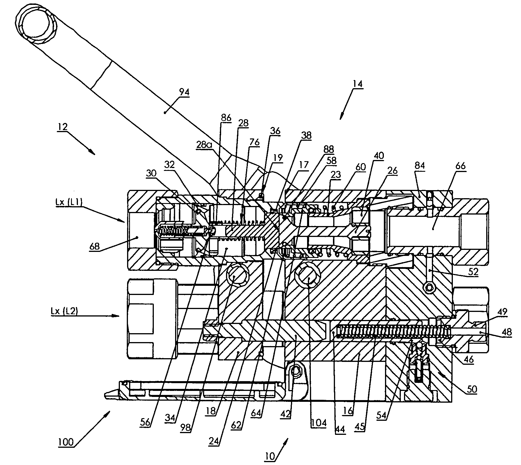
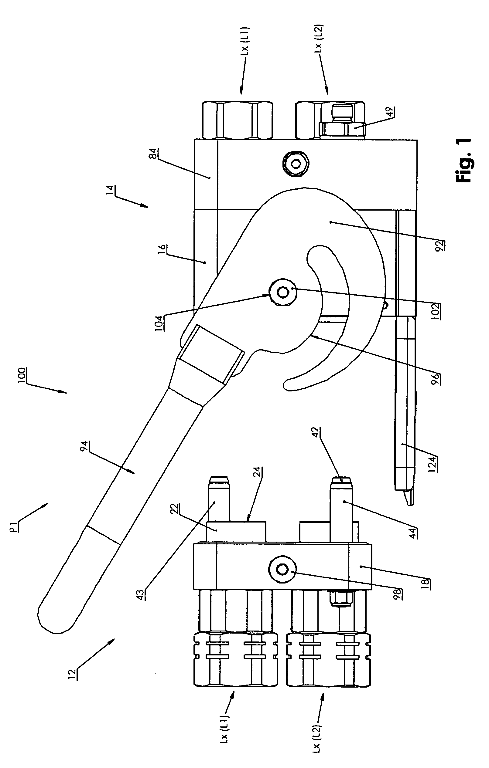
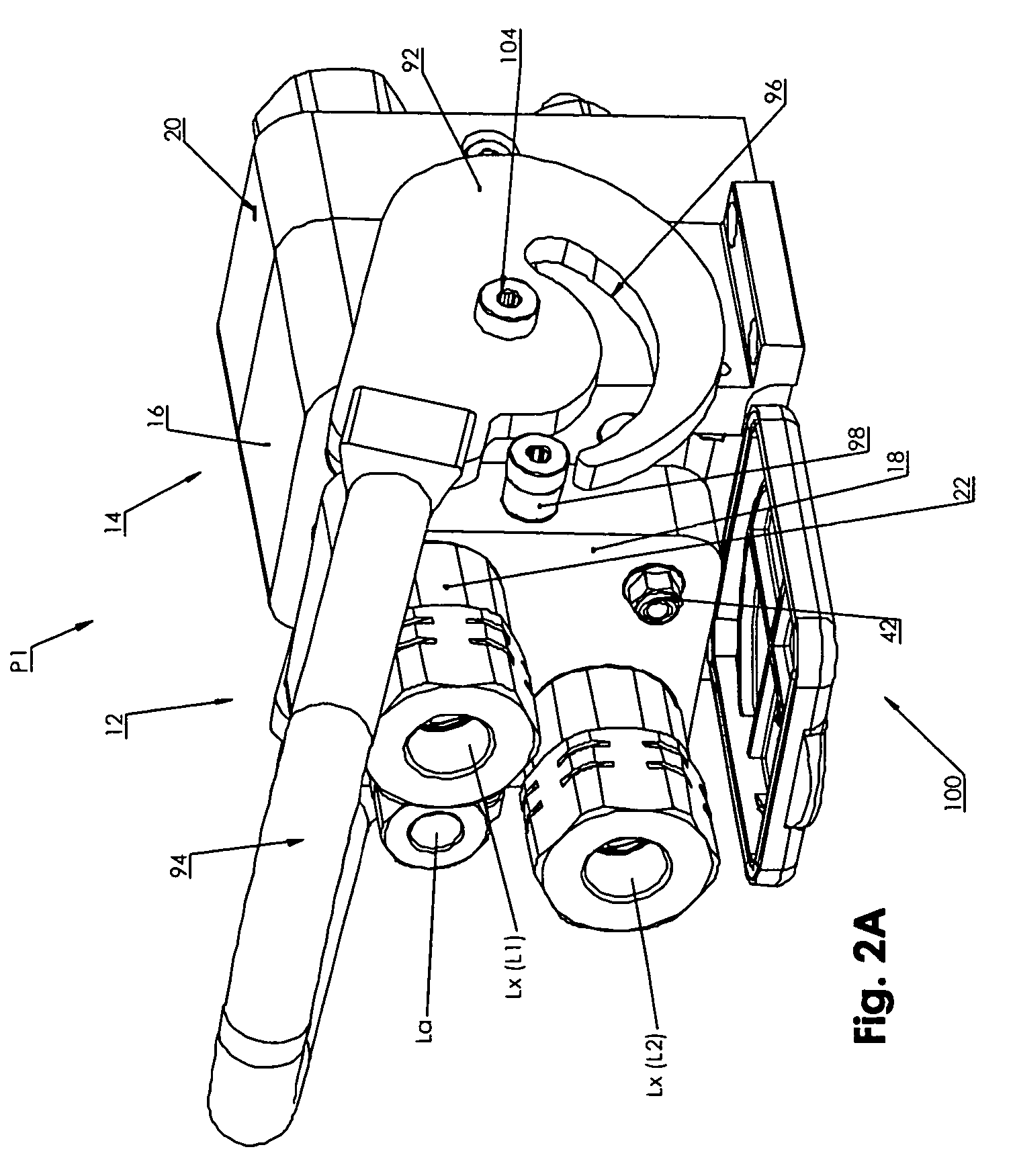
[0049]The quick coupling, overall designated 100, in FIG. 1 shown in the non-coupled state P1, comprises a known basic design comprising two coupling parts 12 and 14. In this arrangement the second coupling part is a plug-in part 12 and the first coupling part 14 is a socket part 14. The special feature of the quick coupling 100 consists of several plug-in parts 12 of several pressurised lines L1, L2 (Lx), which lines are to be connected to each other, being arranged in a second connection block 18.

[0050]The several possible socket parts 14 which face several possible plug-in parts 12 are accommodated in a first connection block 16. FIG. 1 also shows the lines Lx (L1, L2) that lead out of the socket parts 14. Hereinafter a plug-in part 12 and a socket part 14 are designated a coupling pair.

[0051]FIG. 1 thus shows a quick coupling 100 with two couplin...


PUM


Abstract

In order to create a quick coupling for connecting at least two pressurised lines to a first coupling part that is connectable to a second coupling part so as to be pressure-proof, which quick coupling in a simple manner makes possible easy coupling while avoiding the mentioned disadvantages in all pressure ranges, it is provided for an externally arranged central pressure relief device (70) which is integrated in a second coupling part, or arranged on the second coupling part in an additional block (84), to be connectable to the pressurised lines (Lx) by way of pressure-relief connection lines (52A to 52D), and for the coupling parts to be able to be reversibly brought by a lever element (92) from a non-coupled position (P1) to a coupled position (P2), and to be lockable in place.

Description

BACKGROUND OF THE INVENTION[0001]The invention relates to a quick coupling for connecting at least two pressurized lines to a first coupling part that is connectable to a second coupling part so as to be pressure-proof.[0002]Quick couplings (rapid action couplings) of the generic type are well known. They are used to connect pressurised medium-conducting lines, and are used with liquids, for example with hydraulic oils, gases and other suitable media. Normally such quick couplings comprise two coupling parts, wherein a first coupling part is a plug-in part and a second coupling part is a socket part. To bring about coupling, the plug-in part can be pushed into the socket part. The generic quick coupling is also used to connect lines that are subjected to high media pressures. In such cases the connection has to be established one time under pressure in the socket part and another time under pressure in the plug-in part of the coupling. The connection can also be made with both coupl...

Claims


Application Information

Patent Timeline
IPC IPC(8): F16L37/32
CPCF16L37/20F16L37/34F16L37/56Y10S285/924F16L37/18Y10T137/87941Y10T137/87161
Inventor KNUTHSON, PER
Owner TEMA MARKETING
Learn More