Hydraulic four-wheel driving articulated vehicle

a four-wheel drive, hydraulic technology, applied in the direction of transportation and packaging, mechanical equipment, trailer steering, etc., can solve the problems that the stationary steering of the vehicle cannot be smoothly performed, and the conventional hydraulic four-wheel drive articulated vehicle cannot be smoothly steered, so as to achieve smooth steering

Inactive Publication Date: 2008-06-24
KANZAKI KOKYUKOKI MFG
View PDF21 Cites 9 Cited by
  • Summary
  • Abstract
  • Description
  • Claims
  • Application Information

AI Technical Summary

Benefits of technology

[0013]An object of the present invention is to provide a hydraulic four-wheel driving articulate vehicle which can be smoothly steered while it is stationary.
[0014]To achieve the object, a hydraulic four-wheel driving articulate vehicle comprises: a first frame, on which a first axle and a first hydraulic motor driving the first axle are mounted; a second frame, on which a second axle and a second hydraulic motor driving the second axle are mounted, wherein the first and second frames are connected to each other so as to be rotated relatively centering on a vertical axis by a steering operation of the vehicle; and a hydraulic pump. A hydraulic circuit fluidly connects the first and second hydraulic motors in series to the hydraulic pump. The hydraulic circuit includes a passage in which backpressure oil discharged from the first and second hydraulic motors is excessively accumulated when the first and second frames are relatively rotated by the steering operation of the stationary vehicle. The vehicle comprises pressure control means for releasing the excessively accumulated oil from the passage. Due to the oil-releasing of the pressure control means, the first and second hydraulic motors can be freely rotated and can discharge backpressure oil according to the rotation of the first and second axles, thereby enabling smooth steering of the stationary vehicle, i.e., ensuring smooth “stationary steering”.
[0015]Preferably, the released excessive oil is returned to a low-pressure part in the hydraulic circuit. Further preferably, the released excessive pressure oil is drained out from the hydraulic circuit and returned to the hydraulic circuit through a charge valve. Accordingly, loss of oil in the hydraulic circuit is prevented.
[0016]Preferably, the pressure control means includes a pressure control valve, which is opened for releasing the excessive pressure oil while the vehicle is stationary. Such an automatically operated pressure control valve reduces operation labors of an operator.

Problems solved by technology

This is the reason why the conventional hydraulic four-wheel driving articulated vehicle cannot be smoothly steered when it is stationary, i.e., the stationary steering of the vehicle cannot be performed smoothly.

Method used


Image

  • Hydraulic four-wheel driving articulated vehicle
  • Hydraulic four-wheel driving articulated vehicle
  • Hydraulic four-wheel driving articulated vehicle

Examples


second embodiment

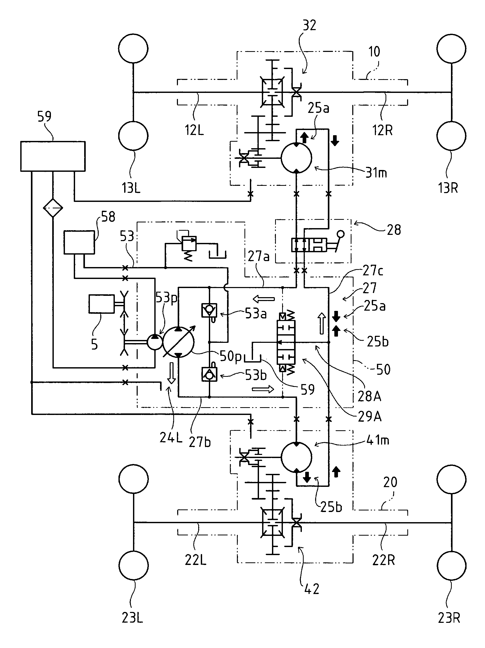
[0069]The hydraulic circuit 27 of FIG. 8 is provided with alternative suitable pressure control means corresponding to the stationary steering operation according to a The pressure control means includes a pressure control valve 29B. The pressure control valve 29B, when being opened, collects the excessive oil from the passages 27a and 27b through respective orifices 35a and 35b, and sends it to the passage 27c (during the stationary steering operation, the hydraulic pressure in the passage 27c is lower than that in the passages 27a and 27b) through a relief passage 28B.

[0070]The pressure control valve 29B is a hydraulic pilot pressure valve having opposite pilot operation portions for receiving opposite pilot pressures extracted from the respective passages 27a and 27b.

[0071]Referring to FIG. 6, while the stationary steering is performed, the backward traveled distance of the front wheels 13L and 13R (the difference between the distances 115L and 115R) is equal to the forward tra...

third embodiment

[0075]The hydraulic circuit 27 of FIG. 9 is provided with alternative pressure control means corresponding to the stationary steering operation according to a The pressure control means includes a pressure control valve 36C, through which a relief passage 28C branches from the passage 27c to the oil tank 59. Alternatively, the relief passage 28C may be extended to the oil-charging passage 53.

[0076]The pressure control valve 36C is a pilot valve, which is closed when it receives a pilot pressure from a portion of the relief passage 28C in communication with the passage 27c. The pilot pressure is generated for closing the pressure control valve 36C when the hydraulic pump 50p discharges oil, so as to increase the hydraulic pressure in the passage 27c and the relief passage 28C, i.e., while the vehicle travels. When the hydraulic pump 50p (the vehicle) is stationary, oil is not circulated in the hydraulic circuit 27 and the hydraulic pressure in the passage 27c is reduced, thereby can...

fourth embodiment

[0078]The hydraulic circuit 27 of FIG. 10 is provided with alternative pressure control means corresponding to the stationary steering operation according to a The pressure control means includes a pressure control valve 36D. The pressure control valve 36D, when being opened, collects the excessive oil from the passages 27a and 27b through respective check valves 37a and 37b, and sends it to the passage 27c (during the stationary steering operation, the hydraulic pressure in the passage 27c is lower than that in the passages 27a and 27b) through a relief passage 28D.

[0079]The pressure control valve 36D is a pilot valve, which is closed when it receives a pilot pressure from the passages 27a and 27b. The pilot pressure is generated for closing the pressure control valve 36D when the hydraulic pump 50p discharges oil, so as to increase the hydraulic pressure in the passage 27a or 27b, i.e., while the vehicle travels. When the hydraulic pump 50p (the vehicle) is stationary, oil is not...


PUM


Abstract

A hydraulic four-wheel driving articulated vehicle comprises: a first frame, on which first axles and a first hydraulic motor driving the first axles are mounted; a second frame, on which second axles and a second hydraulic motor driving the second axles are mounted, wherein the first and second frames are connected to each other so as to be relatively rotatable centering on a vertical axis by a steering operation; a hydraulic pump; a hydraulic circuit fluidly connecting the first and second hydraulic motors in series to the hydraulic pump, wherein the hydraulic circuit includes a passage interposed between the first and second hydraulic motors; and pressure control means for releasing oil from the passage between the first and second hydraulic motors when the first and second frames are relatively rotated by the steering operation of the stationary vehicle and backpressure oil discharged from the first and second hydraulic motors is excessively accumulated in the passage between the first and second hydraulic motors.

Description

BACKGROUND OF THE INVENTION[0001]1. Field of the Invention[0002]The present invention relates to a hydraulic four-wheel driving articulated vehicle having mutually rotatably connected front and rear frames, wherein a hydraulic motor for driving right and left front wheels is mounted on the front frame, a hydraulic motor for driving right and left rear wheels is mounted on the rear frame, and the hydraulic motors are fluidly connected in series to a hydraulic pump. Especially, the present invention relates to construction for smoothing the turning operation of a vehicle body by rotating the front and rear frames while the vehicle is stationary, that is, the operation of so-called “stationary steering”.[0003]2. Related Art[0004]Conventionally, there is a well-known articulated vehicle having mutually rotatably connected front and rear frames 11 and 21 supporting respective transaxles 10 and 20 as shown in FIGS. 1 and 2, and as disclosed in the Japanese Patent Laid Open Gazette 2000-27...

Claims


Application Information

Patent Timeline
Patent Type & Authority Patents(United States)
IPC IPC(8): B62D5/06B60K17/34B60K17/356A01D34/64A01D69/03B62D5/28B62D11/00B62D12/00F16H61/44
CPCA01D69/03B60K17/356B62D5/061B62D11/00B62D12/00F16H61/4043F16H61/4069F16H61/44F16H61/444F16H61/456B60W2540/18
Inventor SAKIKAWA, SHIGENORI
Owner KANZAKI KOKYUKOKI MFG
Why Eureka
Try Eureka