Steering device and vehicle wheel mounting module including the same

a technology of steering device and mounting module, which is applied in the direction of electrical steering, transportation and packaging, propulsion parts, etc., can solve the problems of increasing the size of the steering device, affecting the smooth steering so as to achieve high reduction ratio, high ratio of rotation speed, and not necessarily high efficiency

Active Publication Date: 2020-07-02
TOYOTA JIDOSHA KK
View PDF0 Cites 8 Cited by
  • Summary
  • Abstract
  • Description
  • Claims
  • Application Information

AI Technical Summary

Benefits of technology

[0004]The single-wheel steering device described above is still under development and have various disadvantages. In the disclosed steering device, the output shaft of the speed reducer and the steering knuckle are rigidly coupled, so that inclination of the kingpin axis with respect to the upper arm caused by a bound/rebound movement of the wheel may adversely influence smooth steering. The speed reducer of the disclosed steering device includes a speed reduction mechanism constituted by a face gear and a pinion, and the efficiency is not necessarily high. For obtaining a high reduction ratio, namely, a high ratio of the rotation speed of the input shaft to the rotation speed of the output shaft, the face gear needs to have a larger diameter, inevitably increasing the size of the steering device. To rotate the f

Problems solved by technology

In the disclosed steering device, the output shaft of the speed reducer and the steering knuckle are rigidly coupled, so that inclination of the kingpin axis with respect to the upper arm caused by a bound/rebound movement of the wheel may adversely influence smooth steering.
The speed reducer of the disclosed steering device includes a speed reduction mechanism constituted by a face gear and a pinion, and the efficiency is not neces

Method used


Image

  • Steering device and vehicle wheel mounting module including the same
  • Steering device and vehicle wheel mounting module including the same
  • Steering device and vehicle wheel mounting module including the same

Examples


Embodiment Construction

[0034]Referring to the drawings, there will be explained below in detail a steering device according to one embodiment of the present disclosure and a vehicle wheel mounting module including the steering device. It is to be understood that the present disclosure is not limited to the details of the following embodiment but may be embodied based on the forms described in Various Forms and may be changed and modified based on the knowledge of those skilled in the art.

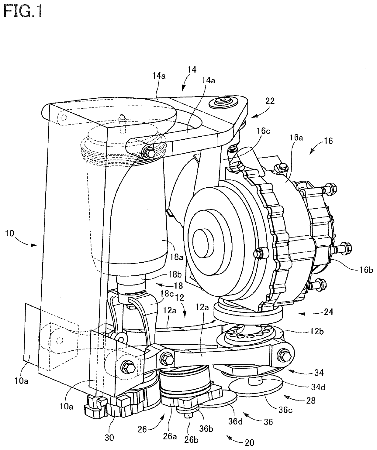
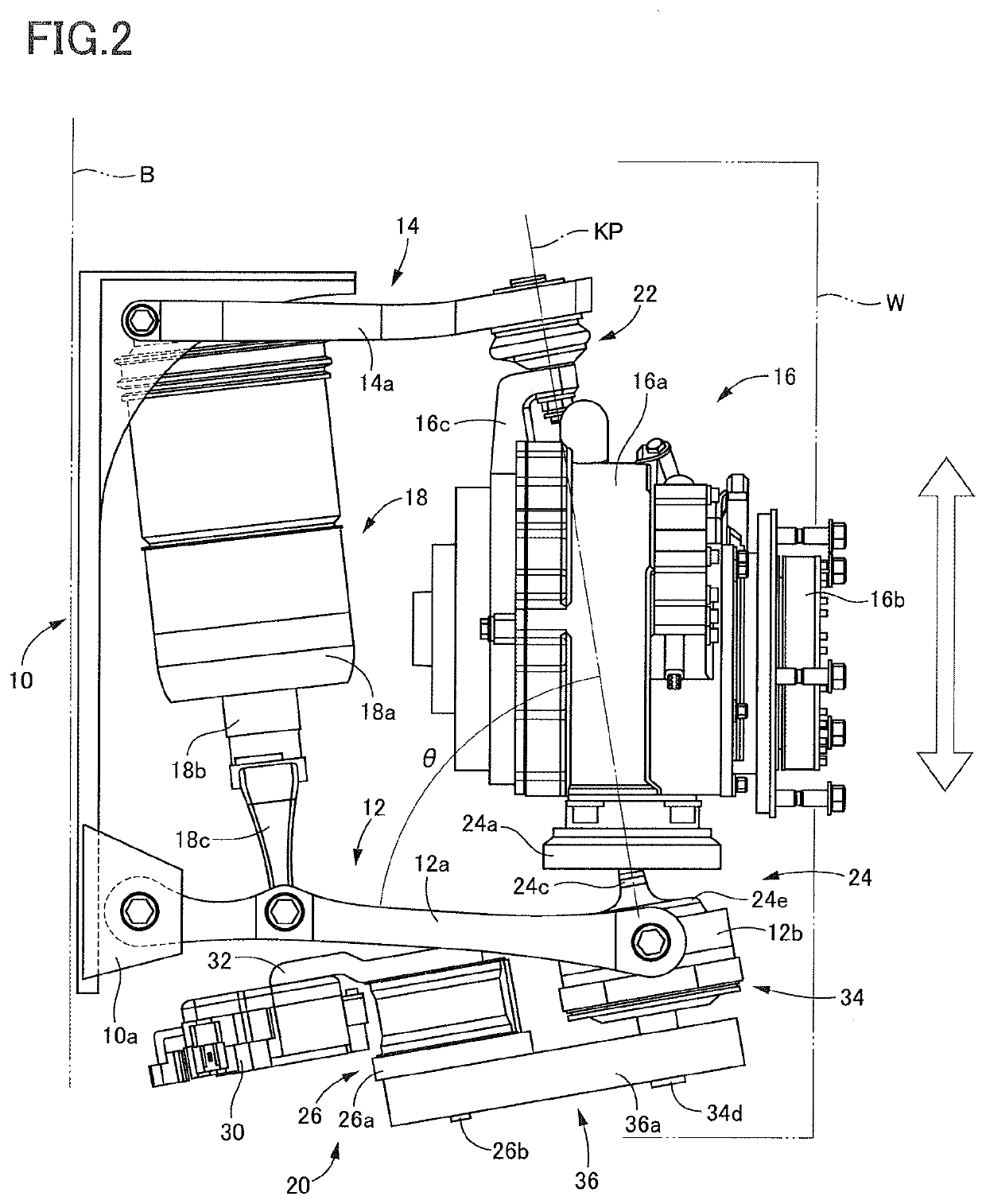
[0035]As shown in FIGS. 1 and 2, the vehicle wheel mounting module according to the present embodiment includes: a base 10 having a rear surface to which is attached a vehicle body B (indicated by the long dashed double-short dashed line in FIG. 2); a lower arm 12, as a first suspension arm, pivotally supported at a proximal end portion thereof by a lower end portion of the base 10; an upper arm 14, as a second suspension arm, pivotally supported at a proximal end portion thereof by an upper end portion of the base 10; a ...


PUM


Abstract

A steering device, including: a steering knuckle rotatably holding a wheel; an electric motor and a speed reducer configured to decelerate rotation of the electric motor, the electric motor and the speed reducer being fixed to a suspension arm; and a joint through which the steering knuckle is supported by the suspension arm in a state in which a kingpin axis is allowed to incline with respect to the suspension arm, the joint coupling the steering knuckle and an output shaft of the speed reducer such that the steering knuckle pivots about the kingpin axis by an operation of the electric motor.

Description

CROSS REFERENCE TO RELATED APPLICATION[0001]The present application claims priority from Japanese Patent Application No. 2018-245243, which was filed on Dec. 27, 2018, the disclosure of which is herein incorporated by reference in its entirety.BACKGROUNDTechnical Field[0002]The following disclosure relates to a steering device configured to steer a wheel and a wheel mounting module for a vehicle which includes the steering device as a constituent element and through which the wheel is mounted on the vehicle.Description of Related Art[0003]A steering device configured to steer only one of a plurality of wheels of a vehicle, namely, a steering device configured to steer only one of right and left wheels, may be referred to as a single-wheel steering device. For instance, Japanese Patent Application Publication No. 2014-169745 discloses a steering device as the single-wheel steering device. The disclosed steering device is configured such that a steering knuckle is supported by a suspe...

Claims


Application Information

Patent Timeline
IPC IPC(8): B62D5/04B62D7/18B60G3/18B60G15/06B60K7/00
CPCB60K7/0007B62D7/18B60G3/18B60G15/06B62D5/046B60G7/006B60G7/02B60K17/043B60K2007/0092B60K2007/0038B62D5/0418B60K11/06B60K11/08B60Y2200/221B60G3/20B60G2200/144B60G2200/44B60G2204/419B60G2300/50
Inventor KURIBAYASHI, TAKUYA
Owner TOYOTA JIDOSHA KK
Why Eureka
Try Eureka