Micro-manipulator

a micro-manipulator and hand-held technology, applied in the field of micro-manipulators, can solve the problems of difficult to stably place the micro-material at a desired position, difficult to separate the micro-material from the gripping finger and place,

Inactive Publication Date: 2008-06-24
TOKYO INST OF TECH +1
View PDF4 Cites 5 Cited by
  • Summary
  • Abstract
  • Description
  • Claims
  • Application Information

AI Technical Summary

Benefits of technology

[0012]In the first aspect, the gripping device has the two gripping fingers. The gripping finger moving device moves at least one of the gripping fingers to grip the micro-material with the gripping fingers of the gripping device. When the gripping finger moving device moves the gripping fingers in opposite directions, the gripping fingers release the micro-material. When the gripping fingers are opened to release the micro-material, the exciting device simultaneously excites the leading ends of the gripping fingers. The gripping finger moving device opens the gripping fingers, while the exciting device simultaneously vibrates both of the leading ends of the gripping fingers gripping the micro-material. Accordingly, when the micro-material is released from the gripping fingers, attraction of a surface force is released, thereby making it possible to place the micro-material at a desired position.
[0013]In the first aspect, the exciting device may have a single piezoelectric element and a vibration transmission member for transmitting vibrations to the leading ends of the gripping fingers from the piezoelectric element. Accordingly, it is not necessary to dispose the piezoelectric element or the vibration transmission member for each of the gripping fingers, thereby making the micro-manipulator small. The vibration transmission member may be branched at the leading ends of the gripping fingers. The exciting device preferably excites the leading ends of the gripping fingers in a direction perpendicular to a direction that the gripping device grips the micro-material, thereby reducing a pressing force on the micro-material.
[0015]In the second aspect, the gripping device has the two gripping fingers. The gripping finger moving device moves at least one of the gripping fingers to grip the micro-material. The detachment finger of the detachment device touches the micro-material gripped by the gripping device, and the gripping finger moving device moves the gripping fingers in a direction perpendicular to the gripping direction, so that the gripping fingers release the micro-material. The exciting device excites a leading end of the detachment finger when the gripping fingers gripping the micro-material are opened. The detachment finger touches the micro-material being gripped by the gripping fingers, and the gripping finger moving device opens the gripping fingers while the exciting device excites the detachment finger. Accordingly, when the micro-material is separated from the gripping fingers and the detachment finger, the attraction of the surface force is released, thereby making it possible to place the micro-material at a desired position.
[0017]According to the first aspect of the present invention, the gripping finger moving device opens the gripping fingers while the exciting device excites the leading ends of the gripping fingers gripping the micro-material. Accordingly, when the micro-material is released from the gripping fingers, the attraction of a surface force is released, thereby making it possible to place the micro-material at an intended position. According to the second embodiment of the present invention, the detachment finger touches the micro-material gripped by the gripping fingers, and the gripping finger moving device opens the gripping fingers while the exciting device vibrates the detachment finger. Accordingly, when the micro-material is released from the gripping fingers and detachment finger, the attraction of a surface force is released, thereby making it possible to place the micro-material at an intended.

Problems solved by technology

Accordingly, when a micro-material is gripped, while it is possible to grip the micro-material without a large force, it is difficult to separate the micro-material from a gripping finger and place the micro-material at a predetermined position.
In the conventional micro-manipulators having two gripping fingers, it is difficult to stably place a micro-material at a desired position because of the surfaces force.
That is, when the two gripping fingers are separated (opened) to release the micro-material, the micro-material tends to stick to one of the gripping fingers, thereby making it difficult to stably place the micro-material at a desired position.

Method used


Image

  • Micro-manipulator
  • Micro-manipulator
  • Micro-manipulator

Examples


first embodiment

[0031]Hereunder, according to a first embodiment of the present invention, a micro-manipulator in a micro-material handling system for handling a micro-material will be explained with reference to the accompanying drawings. According to the first embodiment, leading ends of gripping fingers are excited when opening (or separating) two gripping fingers gripping a micro-material.

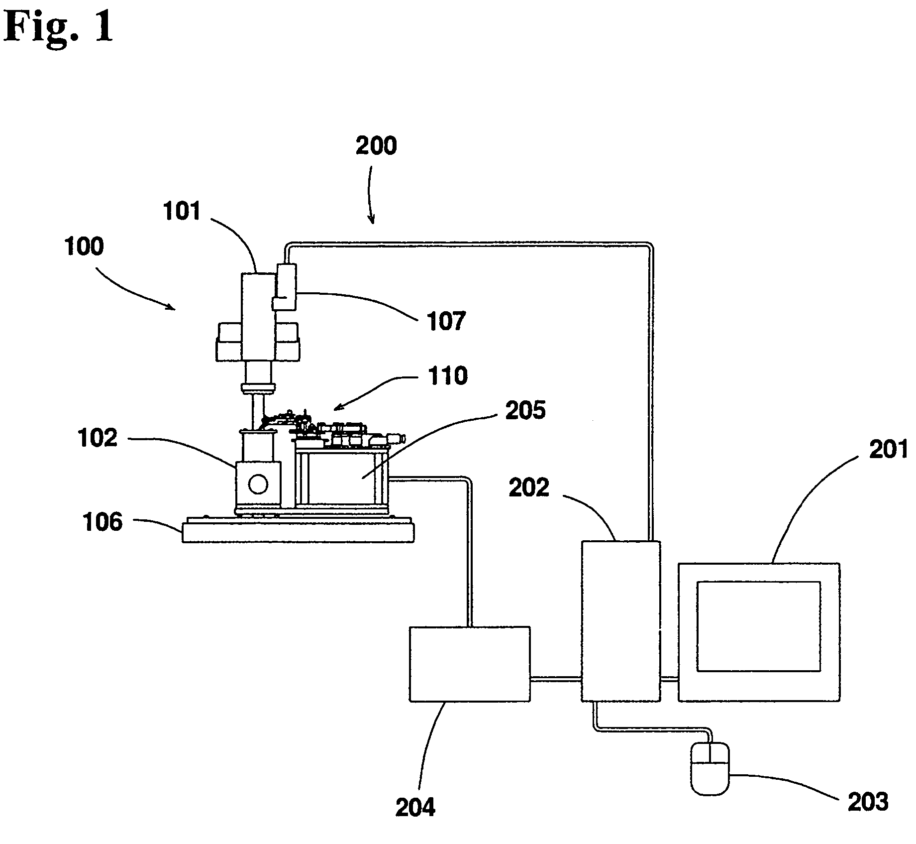
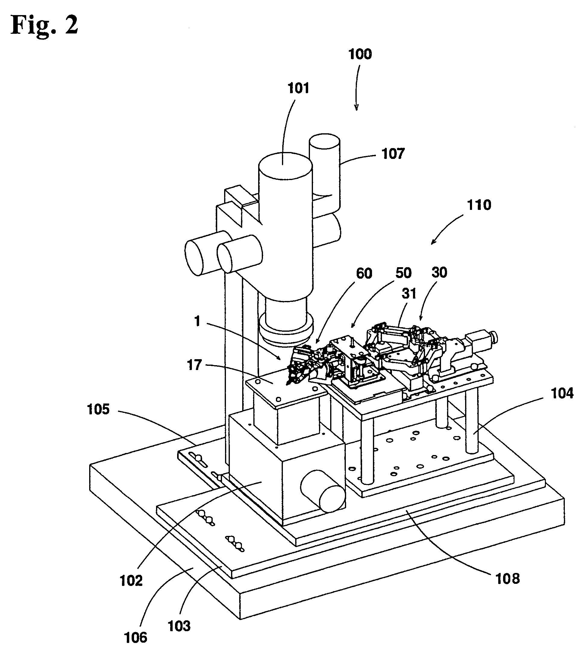
[0032]As shown in FIG. 1, a micro-material handling system 200 of has a micro-material handling device 100 mounted on a thick plate-shaped base 106, and includes a micro-manipulator 110, a micro-material stage 102, and a microscope 101. The micro-material handling system 200 is also equipped with a personal computer (hereinafter referred to as a PC) 202, and a programmable logic controller (hereinafter referred to as PLC) 204 as a slave computer of the PC 202 for controlling the micro-manipulator 110.

[0033]The PC 202 is connected with a liquid crystal display device 201 and an input device 203 such as a mouse....

second embodiment

[0079]According to a second embodiment of the present invention, a micro-manipulator applied to a micro-material handling system for handling micro-materials will be explained below. According to the second embodiment, when opening two gripping fingers for gripping a micro-material, leading ends of the gripping fingers are excited. Note that according to the embodiment of the present invention, the same symbols are applied to configuring members t same as those in the first embodiment of the present invention. Therefore, explanations thereof are omitted and only difference will be described. Furthermore, explanations of actions same as those in the first embodiment of the present pension are omitted.

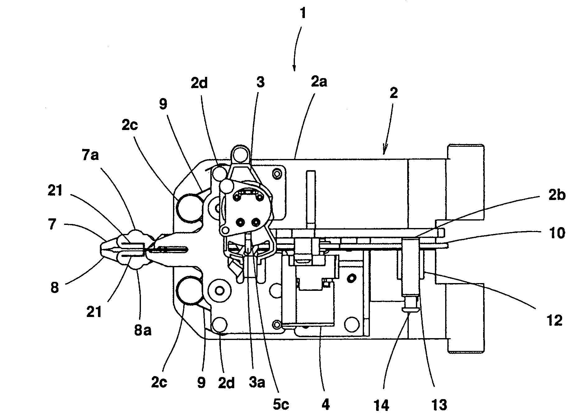
[0080]As shown in FIGS. 12 and 13, a micro-manipulator mechanism 1 of the second embodiment has a member having a shape same as that of the detachment finger 10 in the first embodiment. Instead of the detachment end effecter 11 for pressing the micro-material 20, the detachments finger 1...


PUM


Abstract

A micro-manipulator includes a gripping device having two gripping fingers for gripping a micro-material, and a gripping finger moving device for moving at least one of the gripping fingers of the gripping device. An exciting device vibrates the gripping fingers when the gripping fingers of the gripping device are opened to release the micro-material.

Description

BACKGROUND OF THE INVENTION AND RELATED ART STATEMENT[0001]The present invention relates to a micro-manipulator, and particularly to a micro-manipulator that grips a micro-material with two gripping fingers.[0002]Conventionally, a micro-manipulator is used for assembling a micro-component and handling a cell. Generally, in order to grip a micro-material, a micro-manipulator has a mechanism for opening and closing leading ends of gripping fingers around the micro-material (see Patent Reference 1). The micro-manipulator generally handles a small material in a view of a microscope with naked eyes or through an image on a display via a CCD camera mounted on a microscope (see Patent Reference 2).[0003]When an object has a size in a micro-region less than 1 mm, dominant physical phenomenon are different from those in a macro-region in which a conventional industrial product is handled. In other words, in the micro-region, instead of a dominant force of gravity in the macro-region, forces ...

Claims


Application Information

Patent Timeline
Patent Type & Authority Patents(United States)
IPC IPC(8): B25J7/00G02B21/32B25J15/02
CPCB25J7/00B25J15/0206
Inventor HORIE, MIKIOKAMIYA, DAIKIMOCHIZUKI, NAOTOYODA, YOSHIMICHI
Owner TOKYO INST OF TECH
Why Eureka
Try Eureka