Dual injection manifold

a technology of injection manifold and injection tube, which is applied in the direction of dough shaping, baking, food shaping, etc., can solve the problems of clogging or degradation of the core material

Active Publication Date: 2008-06-24
CENTOCO PLASTICS
View PDF93 Cites 7 Cited by
  • Summary
  • Abstract
  • Description
  • Claims
  • Application Information

AI Technical Summary

Problems solved by technology

The core material may not be heated to the same temperatures as the plastic outer skin material as such temperature may cause clogging or degradation of the core material.

Method used


Image

  • Dual injection manifold
  • Dual injection manifold
  • Dual injection manifold

Examples


Embodiment Construction

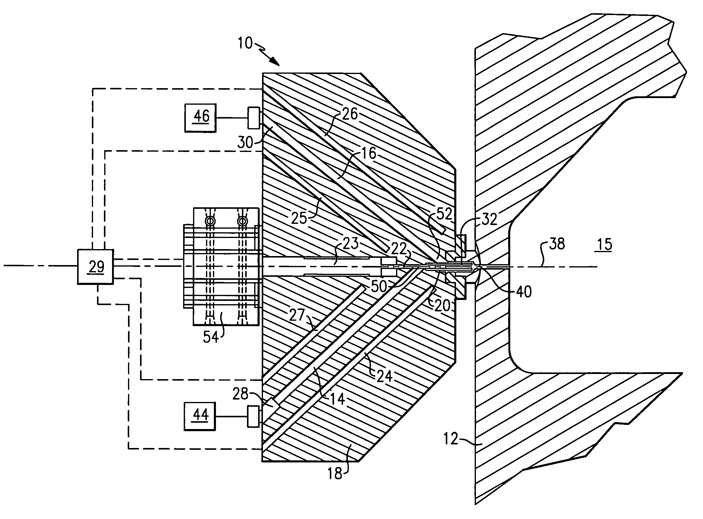
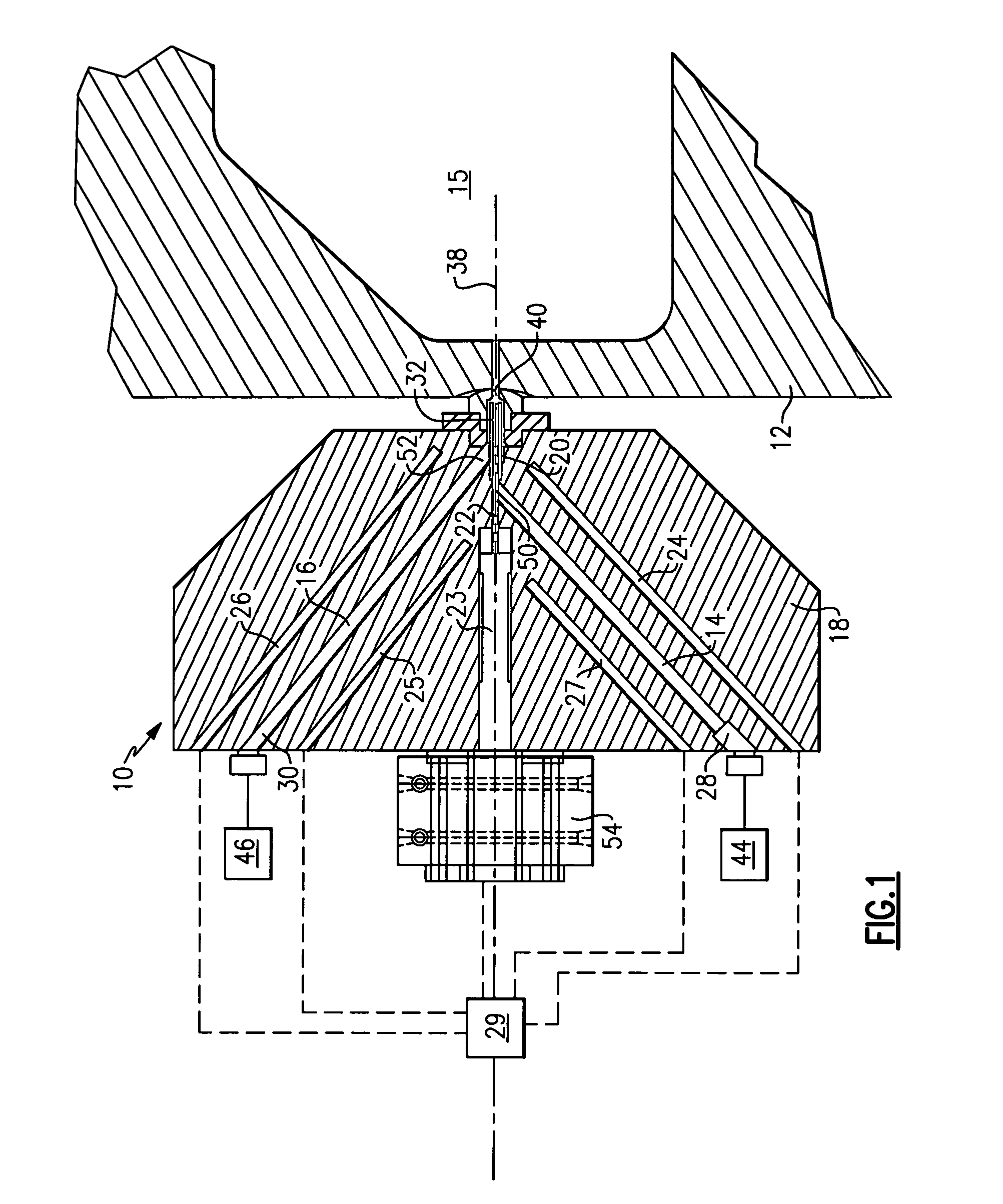
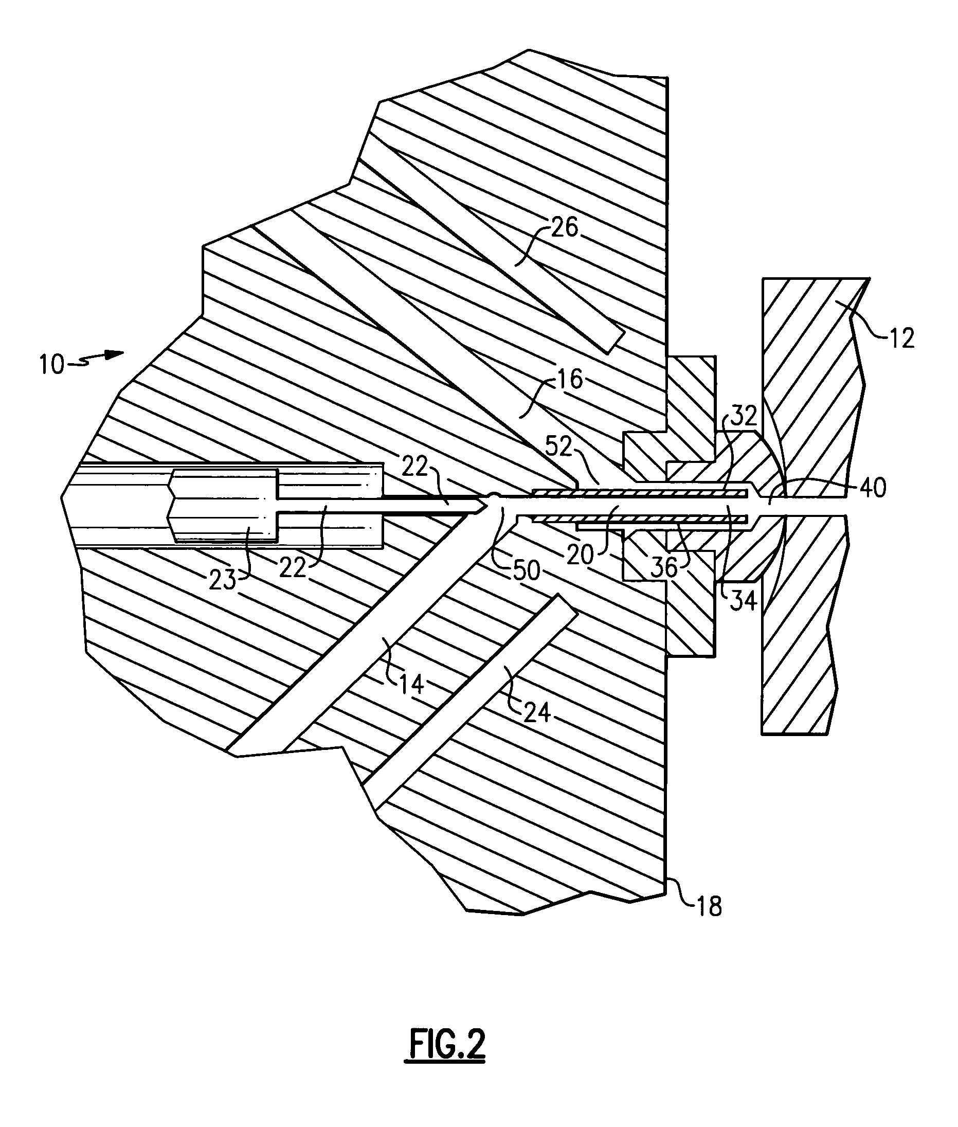
[0031]Referring to FIG. 1, a co-injection manifold assembly 10 includes a first passage 14 and a second passage 16. The first passage 14 and the second passage 16 communicate material from first inlet 28 and second inlet 30 to an outlet 40. Material flows through the outlet 40 into a mold cavity 15 of a mold tool 12. The mold tool 12 can include multiple cavities 15 into which material is injected simultaneously or incrementally. The first and second passages 14, 16 and a bore 20 are defined within a housing 18. The bore 20 is disposed along an axis 38 common with the outlet 40.

[0032]The manifold assembly 10 according to this invention provides for the injection of a core material 44 and a skin material 46. The second skin material 46 is injected first, followed by the core material 44. The core material 44 and skin material 46 are injected into the same mold cavity 15 to provide the desired configuration of a completed molded article. The skin material 46 is injected into the cavit...


PUM

PropertyMeasurementUnit
temperatureaaaaaaaaaa
melting temperaturesaaaaaaaaaa
temperaturesaaaaaaaaaa

Abstract

A co injection manifold assembly for injecting two different materials into a common mold cavity includes a housing that defines a first passage, a second passage and an outlet. The first and second passages communicate with a bore having a valve member for controlling flow of the material through the outlet. A first temperature control element in thermal contact with the first passage and a second temperature control element are in thermal contact with the second passage. Each of the first and second temperature control elements are separately controllable to provide separate temperatures for each of the first and second passages. Separate temperatures in each of the first and second passages provide for the use of materials having dissimilar molten temperatures.

Description

BACKGROUND OF THE INVENTION[0001]This invention relates generally to an injecting unit for a molding machine and more particularly to a co-injecting unit for forming a molded article having an inner core and an outer skin.[0002]A co-injection manifold is typically provided for a molding machine in which a core material and a skin material are concurrently injected into a mold cavity. The core material is typically a different material than the outer skin material. In some instances it may be desirable to use better quality plastic material as the observable outer surface or skin material and a cheaper lesser grade material as the non-visible core material.[0003]Conventional co-injection manifolds include at least two inlets that feed a common outlet leading to the mold cavity. A valve and nozzle control the flow of each material through the outlet and into the mold. The valve provides the desired material flow into the mold and selectively shuts off flow of the core material such th...

Claims


Application Information

Patent Timeline
Patent Type & Authority Patents(United States)
IPC IPC(8): B28B13/00
CPCB29C45/1603B29C45/1642B29C2045/1609B29C2045/2741B29K2105/16B29K2511/14B29K2711/14
Inventor KECK, EDBRIDGEN, DALE E.
Owner CENTOCO PLASTICS
Why Eureka
Try Eureka