
Photonic crystal-loaded zigzag waveguide dual-injection slow-wave structure

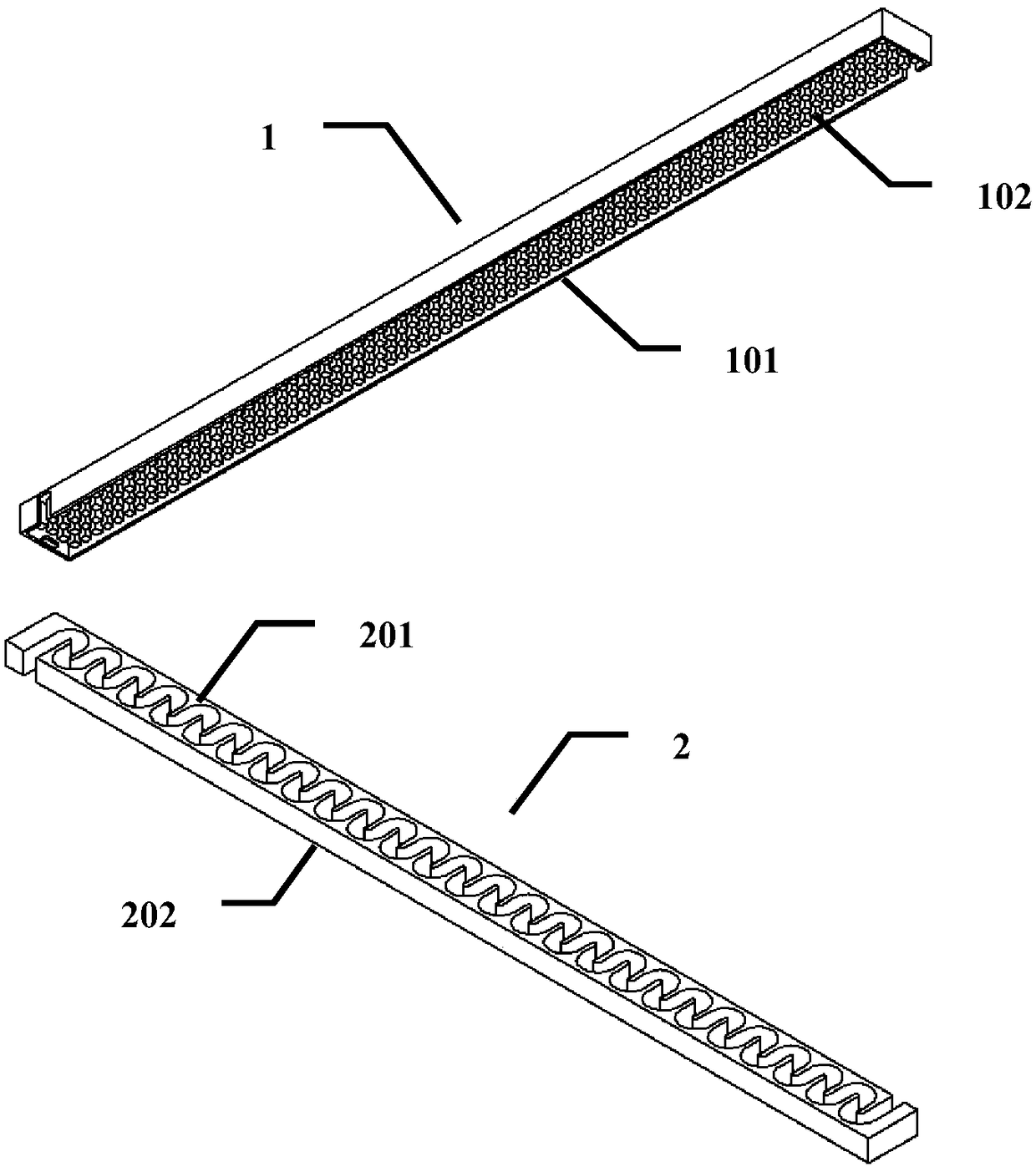
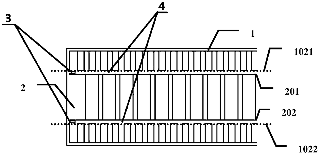
A meandering waveguide and photonic crystal technology, applied in the field of microwave electric vacuum electronic devices, can solve the problems of insufficient concentration of electric field energy and the need to improve the coupling impedance, and achieve the effect of increasing the coupling impedance

Active Publication Date: 2018-07-27
UNIV OF ELECTRONICS SCI & TECH OF CHINA
View PDF5 Cites 6 Cited by
  • Summary
  • Abstract
  • Description
  • Claims
  • Application Information

AI Technical Summary

Problems solved by technology

[0004] Among the existing meandering waveguide traveling wave tubes, such as the slow wave structure of the authorized announcement on December 24, 2014, the announcement number is CN102915898B, and the name is "a meandering waveguide slow wave line", the electronic injection is a single injection, and from the center Vertical transmission, the electric field energy is not concentrated enough, and the coupling impedance needs to be improved

Method used


Image

  • Photonic crystal-loaded zigzag waveguide dual-injection slow-wave structure
  • Photonic crystal-loaded zigzag waveguide dual-injection slow-wave structure
  • Photonic crystal-loaded zigzag waveguide dual-injection slow-wave structure

Examples


Embodiment Construction

[0025] Specific embodiments of the present invention will be described below in conjunction with the accompanying drawings, so that those skilled in the art can better understand the present invention. It should be noted that in the following description, when detailed descriptions of known functions and designs may dilute the main content of the present invention, these descriptions will be omitted here.

[0026] Due to its unique electromagnetic properties, photonic crystals have attracted the attention of scholars all over the world. Photonic crystal technology has been applied in microwave circuit filters, thresholdless lasers and high-performance superprisms and other fields.

[0027] The invention applies the photonic crystal technology to the field of microwave electric vacuum electronic devices, utilizes the bandgap characteristic of the photonic crystal, and the electromagnetic wave propagates in the far region outside the open broadside of the broadside open meanderin...


PUM


Abstract

The invention discloses a photonic crystal-loaded zigzag waveguide dual-injection slow-wave structure; by virtue of a forbidden band characteristic of a photonic crystal structure, propagation of electromagnetic wave in a relatively distant region outside the open broadside of the broadside open zigzag waveguide can be blocked; equivalently, the waveguide cavity space of the conventional zigzag waveguide propagated by adopting a TE20 mode is reduced, so that electric field energy can be more concentrated, thereby realizing establishment of a larger electric field at the same input power, and coupled impedance of a slow-wave structure is increased; the electric field structure in the broadside open zigzag waveguide is equivalent to a part of the electric field in the conventional zigzag waveguide, and has the dispersion characteristic similar to that of the conventional zigzag waveguide; and equivalently, the photonic crystal-loaded zigzag waveguide dual-injection slow-wave structure has similar dispersion characteristic and bandwidth as the conventional zigzag waveguide adopting the TE20 mode.

Description

technical field [0001] The invention belongs to the technical field of microwave electric vacuum electronic devices, and more specifically relates to a meandering waveguide double-injection slow wave structure loaded with photonic crystals. Background technique [0002] As a microwave power amplifier device with a wide range of applications, traveling wave tubes have a very rich variety of products in both military and civilian fields. [0003] Currently commonly used traveling wave tube types are: helical traveling wave tube, coupled cavity traveling wave tube, meandering waveguide traveling wave tube and so on. Among them, generally speaking, the meandering waveguide traveling wave tube has relatively moderate bandwidth and coupling impedance, and has very broad development prospects in the commonly used microwave frequency band. [0004] Among the existing meandering waveguide traveling wave tubes, such as the slow wave structure of the authorized announcement on Decembe...

Claims


Application Information

Patent Timeline
IPC IPC(8): H01J23/24
CPCH01J23/24
Inventor 师凝洁许多宫玉彬王战亮巩华荣魏彦玉段兆云
Owner UNIV OF ELECTRONICS SCI & TECH OF CHINA
Learn More