Compact type narrow-band high-power microwave source for forced stopping of vehicles

A high-power microwave, compact technology, applied in the direction of weapon types, offensive equipment, etc., which can solve light, small and high-efficiency technical solutions has not been publicly reported, and few mature and simple solutions and systems have been seen. Low energy conversion efficiency and other issues, to achieve the effect of improving beam action efficiency, high miniaturization, and improving quality factors

Active Publication Date: 2020-02-18
深圳市思博克科技有限公司
View PDF9 Cites 4 Cited by
  • Summary
  • Abstract
  • Description
  • Claims
  • Application Information

AI Technical Summary

Problems solved by technology

[0008] Analyzing the above research status, it is not difficult to see that the research on the L-band relativistic Cerenkov oscillator has made great progress, but there are the following deficiencies: five slow-wave blades are usually used, and the axial length is relatively long, resulting in the guide The magnetic field is long, which is not conducive to the miniaturization of devices; the power conversion efficiency is usually around 30%, and the energy conversion efficiency of the system is low
[0009] Therefore, although people have begun to study compact L-band relativistic Cerenkov oscillators, few mature and simple solutions have been seen, especially the technical solutions for simultaneously realizing light, small and high-efficiency devices have not yet been disclosed. report

Method used


Image

  • Compact type narrow-band high-power microwave source for forced stopping of vehicles
  • Compact type narrow-band high-power microwave source for forced stopping of vehicles
  • Compact type narrow-band high-power microwave source for forced stopping of vehicles

Examples


Embodiment Construction

[0033] The accompanying drawings constituting a part of this application are used to provide further understanding of the present invention, and the schematic embodiments and descriptions of the present invention are used to explain the present invention, and do not constitute an improper limitation of the present invention.

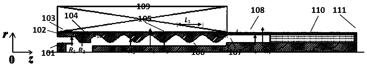
[0034] figure 1 It is a structural schematic diagram of the compact L-band coaxial relativistic Cerenkov oscillator disclosed in prior art 1. The structure is composed of a cathode seat 101, a cathode 102, an anode outer cylinder 103, a cut-off neck 104, an outer slow wave structure 105, an inner slow wave structure 106, a collector 107, an output waveguide 108, a solenoid magnetic field 109, and a wave-absorbing medium 110 , and support rods 111, and the entire structure is rotationally symmetrical about the central axis. Although the paper publishes the simulation results, it only gives a schematic diagram of the structure without a specific technica...


PUM


Abstract

The invention relates to a microwave source device in the technical field of high-power microwaves, in particular to a compact type narrow-band high-power microwave source for forced stopping of vehicles. The compact type narrow-band high-power microwave source comprises a cathode base, a cathode, an anode outer cylinder, a cut-off neck, an outer slow wave structure, an inner slow wave structure,an output waveguide, a coaxial extraction section, an isolation section, a resonant reflection ring, a rear resonant cavity, a solenoid magnetic field and a supporting rod, and the whole structure isrotationally symmetrical with the central axis. The compact type narrow-band high-power microwave source has the advantages that by using the rear resonant cavity, it is ensured that miniaturization and high efficiency are achieved, a peak value with an optimal effect can be generated on the beam-wave effect, and long pulses are easily achieved. By using the resonant reflection ring, the peak value with the optimal effect can be generated on the beam-wave effect; by using the inner and outer double corrugated rectangular slow wave structures, the radial dimension of the outer slow wave structure is reduced; the inner slow wave structure is of a rectangular structure, and the inner slow wave structure and the outer slow wave structure form the double-rectangular structure, so that the axiallength is shortened.

Description

technical field [0001] The invention relates to a microwave source device in the technical field of high-power microwaves, in particular to a compact narrow-band high-power microwave source used for emergency parking of vehicles and ships. Background technique [0002] At present, high-power microwaves (usually referring to electromagnetic waves with a peak power greater than 100 MW and a frequency between 1 and 300 GHz) are used in directed energy weapons, power supply for satellites and space platforms, launch of small deep space probes, altitude change propulsion systems of orbiters, Electronic high-energy radio frequency accelerators, material processing and processing are widely used in national defense and industrial fields. The high-power microwave source is the core subsystem of the high-power microwave system, which is used to generate high-power microwaves of different frequencies. [0003] In recent years, developed countries represented by the United States and ...

Claims


Application Information

Patent Timeline
Patent Type & Authority Applications(China)
IPC IPC(8): F41H13/00
CPCF41H13/0068
Inventor 于学尧
Owner 深圳市思博克科技有限公司
Why Eureka
Try Eureka