Welding jig for spiral line of traveling-wave tube

A welding jig and helix technology, applied in the field of traveling wave tube welding jig

Active Publication Date: 2014-08-20
CHENGDU GUOGUANG ELECTRIC
View PDF8 Cites 4 Cited by
  • Summary
  • Abstract
  • Description
  • Claims
  • Application Information

AI Technical Summary

Problems solved by technology

The slow wave part of the traveling wave tube will generate heat due to a small amount of irregular electrons. If this part of the heat cannot be effectively transmitted and dissipated, it will have an adverse effect on the working environment of the traveling wave tube and affect the working stability of the traveling wave tube. In severe cases It will also damage the traveling wave tube. Therefore, the heat dissipation of the slow wave is very important. The welding helix structure of the slow wave part of the existing traveling wave tube can make the distance between the helix and the clamping rod, between the clamping rod and the shell The thermal resistance is reduced, thereby improving the heat dissipation capacity of the slow wave, but the welding helix structure of most existing traveling wave tubes is a structure welded with the helix and the slow wave transition strip through the clamping rod, and the traveling wave of this structure The tube can improve the heat dissipation capacity of the slow wave, but it affects the electronic interaction efficiency of the traveling wave tube, and then affects the electronic efficiency of the whole tube of the traveling wave tube. A traveling wave tube with a welded helical structure that maintains the efficiency of electronic interaction. This traveling wave tube includes a helix, a slow wave transition strip, and a shell. The slow wave transition strip and the helix are located inside the shell and along the axial direction inside the shell. set, and the helix is ​​coaxial with the tube shell, the slow wave transition strip is located between the helix and the tube shell, the welded helical structure of the traveling wave tube also includes a block-shaped clamping block, the The clamping block is located between the slow-wave transition strip and the helix, and the surface of the clamping block in contact with the slow-wave transition strip and the helix is ​​plated with weldable metal, and the clamping block, the slow-wave transition strip and the helix pass through the easy-weldable metal Welded together, the clamping blocks are distributed at intervals of 120° in the circumferential direction of the helix cross-section, and the adjacent clamping blocks in the direction of the helix axis are not connected to each other (see Figure 1 and Figure 2)
However, the helical welding process of this structure traveling wave tube is complex and cumbersome, and the welded helix is ​​not easy to meet the design requirements.

Method used


Image

  • Welding jig for spiral line of traveling-wave tube
  • Welding jig for spiral line of traveling-wave tube
  • Welding jig for spiral line of traveling-wave tube

Examples


Embodiment 1

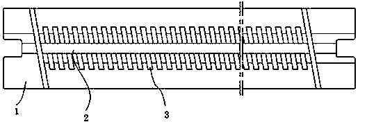
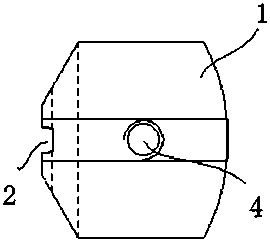
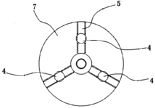
[0025] The traveling wave tube helical wire welding fixture described in this embodiment includes a positioning block, a positioning plate, a spacer, and a screw; the positioning block is three cylinders with central angles of 120° cut by a cylinder, The 120° center of the positioning block is provided with a slow-wave transition strip fixing groove and a plurality of spacer fixing grooves upward along the positioning block axis, and the spacer fixing grooves are parallel to each other and intersect with the slow-wave transition strip fixing groove , the angle between the fixed groove of the spacer and the fixed groove of the slow wave transition strip is consistent with the clamping angle between the slow wave transition strip of the traveling wave tube and the helix; the spacer is placed in the fixed groove of the spacer; the Both ends of the positioning block and the positioning plate are provided with threaded holes and / or pin holes, and the positioning plate can be fixed a...

Embodiment 2

[0028] The second embodiment is to add a base on the basis of the traveling wave tube helical wire welding fixture described in the first embodiment, and the base is provided with a groove matching the shape of the positioning block, and the positioning block can be placed on the base To facilitate the installation of the positioning block and place the fixed positioning block on the base and then put it into the hydrogen furnace for heating and welding.

[0029] Using the traveling wave tube helical wire welding jig described in this embodiment can effectively and reliably weld multiple clamping blocks with the designed clamping angle with the helical wire and the slow wave transition strip, so that the helical wire assembly and welding process is simple and easy to operate . The traveling wave tube welded by the traveling wave tube helical wire welding fixture reduces the loading, increases the coupling impedance, and improves the electronic efficiency


PUM


Abstract

The invention discloses a welding jig for a spiral line of a traveling-wave tube. The welding jig for the spiral line of the traveling-wave tube comprises a positioning block, positioning plates, partition blocks and screws, wherein the positioning block is composed of three cylindrical bodies which are formed by cutting a cylinder, the three central angles between the cylindrical bodies are 120 degrees, a slow wave transition strip fixing groove and multiple partition block fixing grooves are formed in the 120-degree circle center position of the positioning block in the axial direction of the positioning block, the partition block fixing grooves are parallel to one another and intersect with the slow wave transition strip fixing groove, and the included angle between each partition block fixing groove and the slow wave transition strip fixing groove is equal to the included angle between a slow wave transition strip and the spiral line of traveling-wave tube. By the adoption of the welding jig for the spiral line of the traveling-wave tube, the spiral line assembly welding technology is made simple, and operation is convenient.

Description

technical field [0001] The invention relates to an assembly fixture, in particular to a traveling wave tube welding fixture. Background technique [0002] Traveling wave tube is a microwave electric vacuum power device, which mainly plays the role of final stage amplification in microwave signal system, and has a wide range of applications. Traveling wave tube has the characteristics of wide frequency range, high gain, large dynamic range and low noise, and has become an important microwave device for electronic equipment such as radar, electronic countermeasures, relay communication, satellite communication, live TV satellite, navigation, remote sensing, remote control, and telemetry. . The slow wave part of the traveling wave tube will generate heat due to a small amount of irregular electrons. If this part of the heat cannot be effectively transmitted and dissipated, it will have an adverse effect on the working environment of the traveling wave tube and affect the worki...

Claims


Application Information

Patent Timeline
Patent Type & Authority Applications(China)
IPC IPC(8): B23K37/04
CPCB23K37/0443
Inventor 李国
Owner CHENGDU GUOGUANG ELECTRIC
Why Eureka
Try Eureka