Rotation angle detector

a detector and rotation angle technology, applied in the field of rotation angle detectors, can solve the problems of increasing production costs, increasing the cost and size of the circuit used in the rotation angle detector, and needing complicated calculation operations, etc., and achieves high resolution.

Inactive Publication Date: 2008-06-24
DENSO CORP
View PDF32 Cites 13 Cited by
  • Summary
  • Abstract
  • Description
  • Claims
  • Application Information

AI Technical Summary

Benefits of technology

[0009]In view of the above-described and other problems, it is an object of the present invention to provide a rotation angle detector having a hall element for detecting rotation of the magnetic field in a high resolution with an advantage in both the size and the production cost.

Problems solved by technology

However, the difference of the phases between the hall voltages Va and Vb makes it necessary to use a complicated calculation operation such as the arctangent operation or the like.
Therefore, an operation circuit for processing those operations increases both cost and size of the circuit used in the rotation angle detector 90.
The increase in size of the operation circuit leads to an increased cost of production.

Method used


Image

  • Rotation angle detector
  • Rotation angle detector
  • Rotation angle detector

Examples


first embodiment

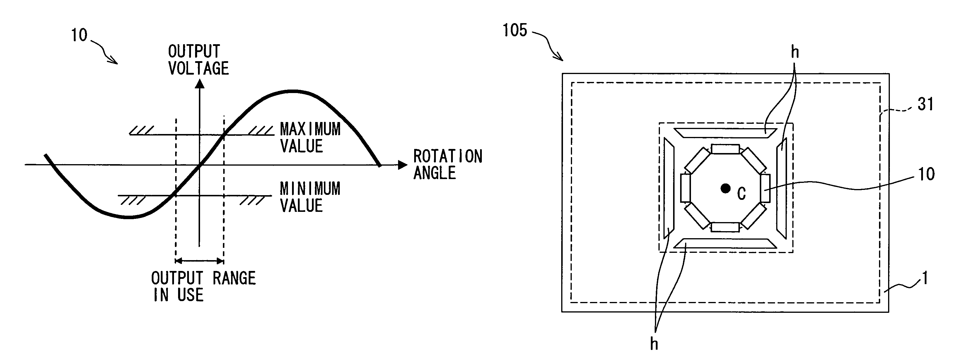
[0067]FIG. 4A shows a top view of a rotation angle detector 100 in a first embodiment of the present invention. FIG. 4B shows a diagram of relationship between the rotation angle of a magnetic field and the output voltage from each of hall elements 10 in the detector 100.

[0068]The rotation angle detector 100 detects the rotation angle of the magnetic field represented by a thick arrow in FIG. 4A. The magnetic field (magnetic flux density B), or the thick arrow, rotates in a plane that is perpendicular to a surface of the semiconductor substrate 1. As shown in FIG. 4A, the semiconductor substrate 1 has the eight hall elements 10 equiangularly disposed in a ring shape around a rotation axis C of the magnetic field on one side of the substrate 1. More practically, the vertical hall element shown in FIGS. 3A and 3B or the slant type hall element shown in FIGS. 13A and 13B are used as the hall element 10. Number of hall plate portions may be at least one on either of the two slope of the...

second embodiment

[0085]The rotation angle detector in a second embodiment detects the rotation angle of the magnetic field rotating in a plane that is perpendicular to the surface of the semiconductor substrate 1.

[0086]FIGS. 11A to 11C and 12 show perspective views of portions of cross sections of rotation angle detectors 200 to 203.

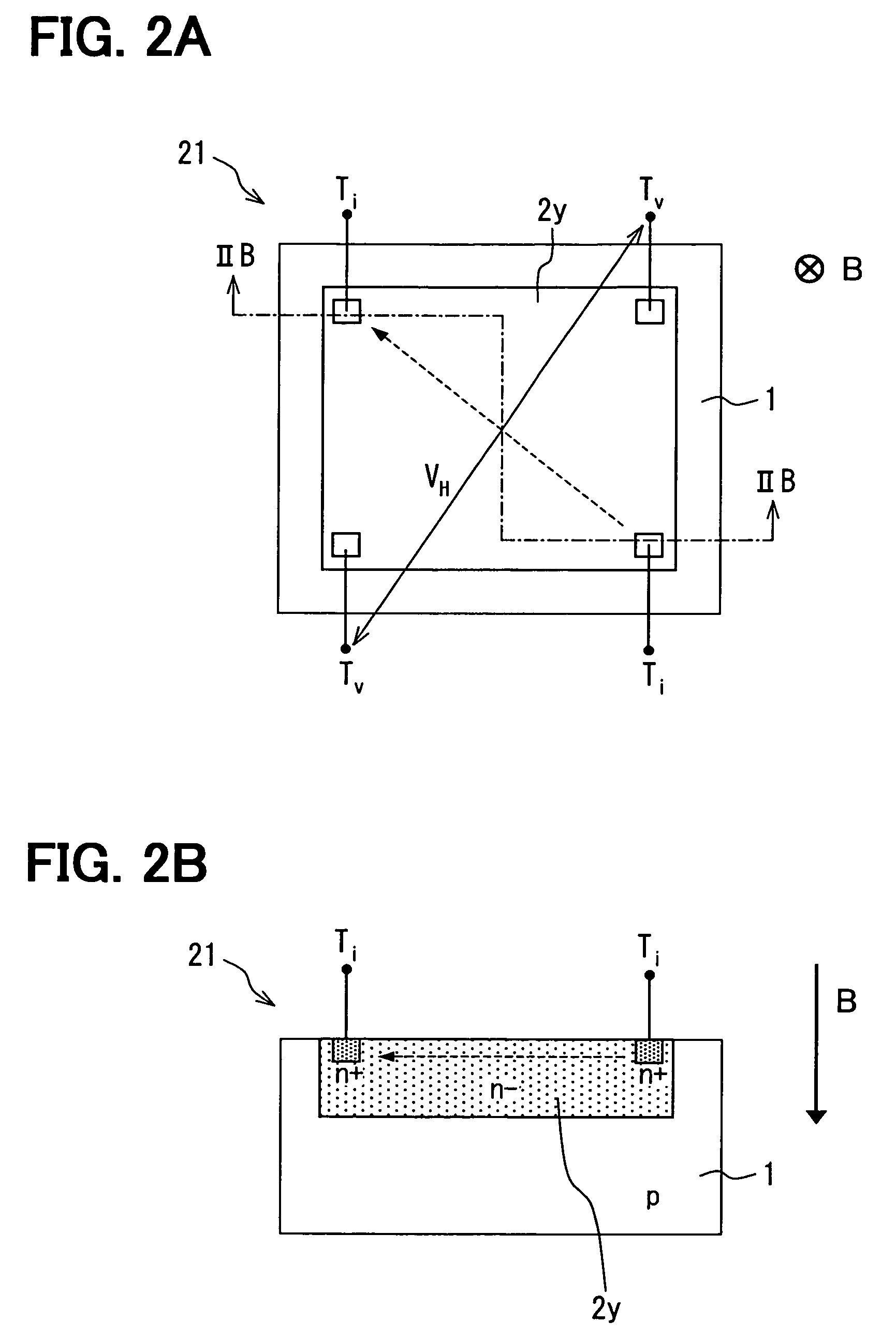
[0087]The rotation angle detectors 200 to 203 are used for detecting the rotation angle of the magnetic field (magnetic flux density B) rotating in a plane that is perpendicular to the surface of the semiconductor substrate 1. The rotation angle detector 200 shown in FIG. 11A includes both of the horizontal type hall elements 21 in FIGS. 2A and 2B and the vertical hall elements 22 in FIGS. 3A and 3B. The rotation angle detector 201 shown in FIG. 11B includes both of the slant type hall elements 23 in FIGS. 13A and 13B and the horizontal type hall elements 21. The rotation angle detector 202 includes the slant type hall elements 23 and the vertical hall elements 22. The r...


PUM


Abstract

A rotation angle detector detects a rotation angle of a magnetic field by selectively using a hall element from a plurality of hall elements disposed on one side of a semiconductor substrate. The hall elements are equiangularly disposed to each other in a ring shape. The rotation angle of the magnetic field is detected by using a portion of an output signal of the hall element having a substantially linear output characteristic.

Description

CROSS REFERENCE TO RELATED APPLICATION[0001]This application is based on and claims the benefit of priority of Japanese Patent Application No. 2004-231341 filed on Aug. 6, 2004, and Japanese Patent Application No. 2005-151589 filed on May 24, 2005, the disclosure of which is incorporated herein by reference.FIELD OF THE INVENTION[0002]The present invention generally relates to a rotation angle detector for detecting a rotation angle of an object of interest.BACKGROUND OF THE INVENTION[0003]In recent years, a rotation angle detector is developed and disclosed. For example, a rotation angle detector for detecting a rotation angle based on a detected angle of rotation of a magnetic field is disclosed in transactions of ‘Transducers 93’ The 7th International Conference on Solid-State Sensors and Actuators, p.p.892 to 895, and in Japanese Patent Document JP-A-H4-302406.[0004]FIGS. 13A and 13B show illustrations of a rotation angle detector 90 disclosed in the above Japanese Patent Docume...

Claims


Application Information

Patent Timeline
Patent Type & Authority Patents(United States)
IPC IPC(8): G01B7/30G01R33/06H01L43/08
CPCG01D5/145G01R33/077
Inventor OOHIRA, SATOSHI
Owner DENSO CORP
Why Eureka
Try Eureka