Parametric programmable thermal printer

a thermal printer and parametric technology, applied in printing and other directions, can solve the problems of undesirable differences in rendering intensity, difficult to achieve, and difficult to achieve the effect of retaining hea

Inactive Publication Date: 2008-06-24
ZINK IMAGING
View PDF17 Cites 12 Cited by
  • Summary
  • Abstract
  • Description
  • Claims
  • Application Information

AI Technical Summary

Problems solved by technology

One problem with conventional thermal printers results from the fact that their print head elements retain heat after the conclusion of each print head cycle.
This retention of heat can be problematic because, in some thermal printers, the amount of energy that is delivered to a particular print head element during a particular print head cycle is typically calculated based on an assumption that the print head element's temperature at the beginning of the print head cycle is a known fixed temperature.
Further complications are similarly caused by the fact that the current temperature of a particular print head element is influenced not only by its own previous temperatures—referred to herein as its “thermal history”—but by the ambient (room) temperature, the thermal histories of other print head elements in the print head, and the temperature of the output medium (film / media) and other thermal printer elements, such as the platen roller and the preheat contact with the thermal heat sink of the Thermal Print Head (TPH).
This difference in rendered intensity is undesirable because it corresponds to the number of contemporaneously active print head elements, rather than to the intensities of the pixels in the source image being printed.
The result is a printed image having undesired variations in intensity that do not accurately reflect the intensities of the pixels in the source image being printed.
Integrating these and other features of a thermal printer into a single thermal imaging system presents a variety of challenges.
Such redesign is tedious, time-consuming, and expensive.

Method used


Image

  • Parametric programmable thermal printer
  • Parametric programmable thermal printer
  • Parametric programmable thermal printer

Examples


Embodiment Construction

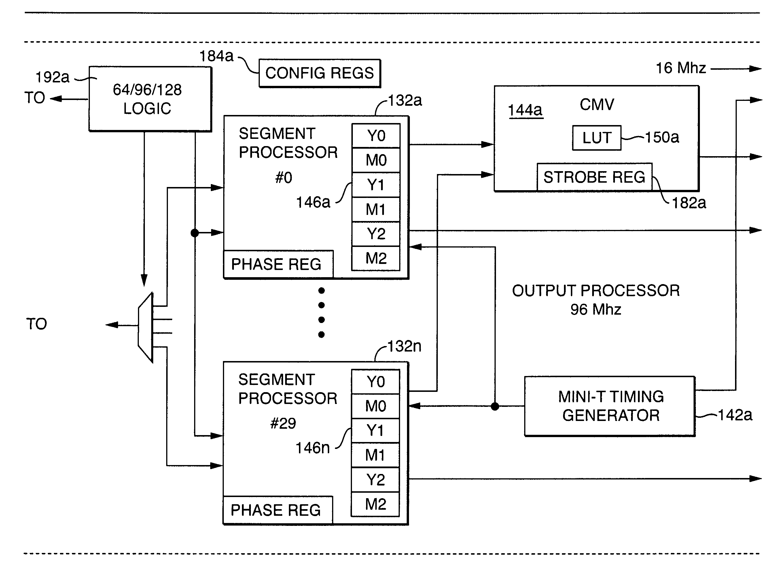
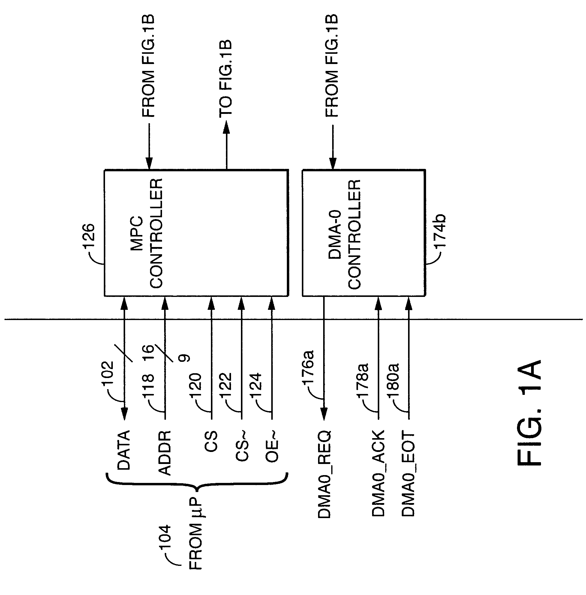
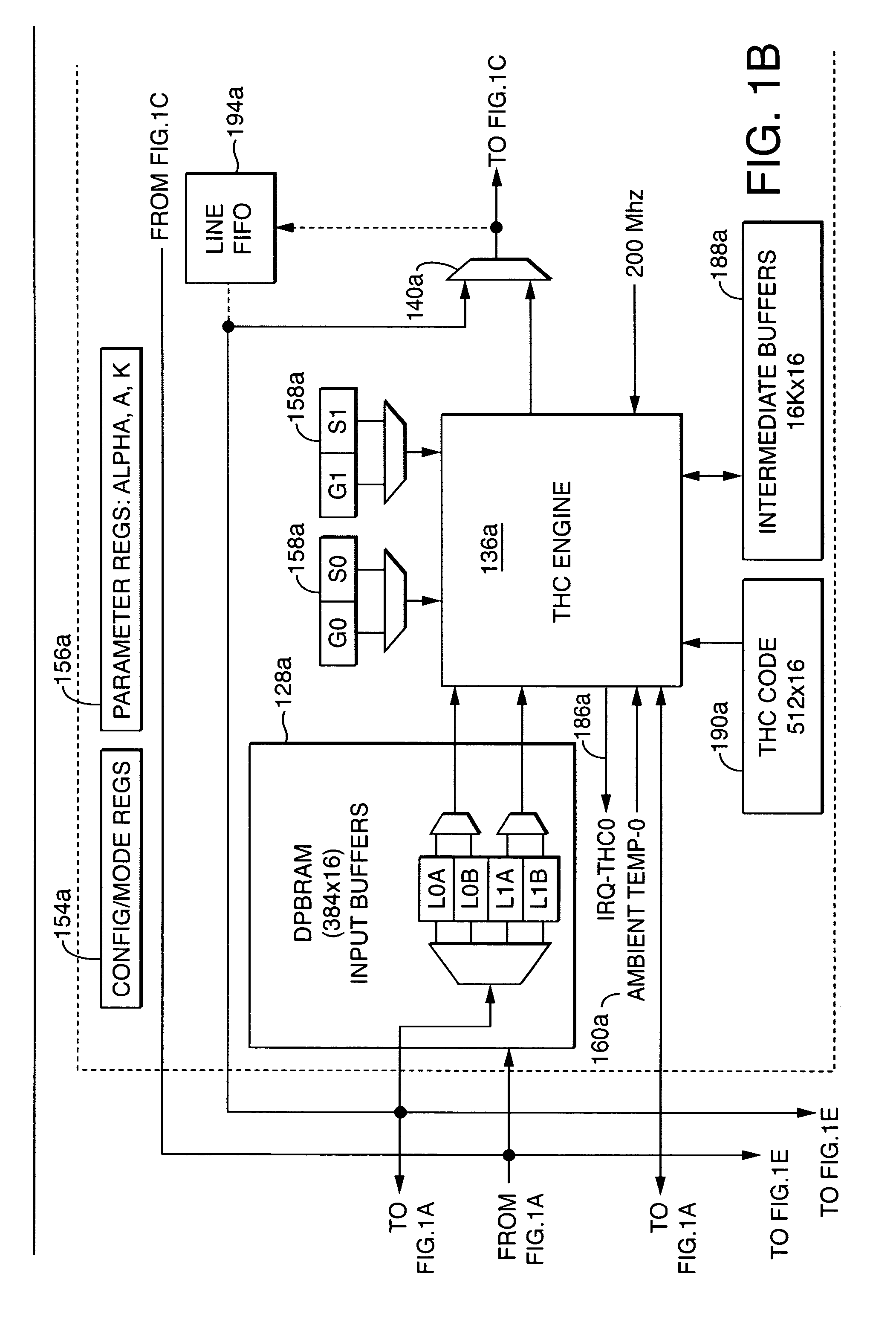
[0022]A parametric programmable thermal printer is disclosed. The printer may include a controller that performs functions such as thermal history control and common mode voltage correction. The controller may be implemented in an integrated programmable medium such as a Field-Programmable Gate Array (FPGA). Functions performed by the controller may be parameterized, and parameter values may be stored in registers. The controller may be used with a different thermal printer by changing the parameter values and / or reprogramming the programmable medium, and without otherwise redesigning or remanufacturing the controller.

[0023]Referring to FIGS. 1A-1J, block diagrams are shown of a thermal print head controller 100 according to one embodiment of the present invention. FIGS. 1A-1J may be referred to collectively herein as FIG. 1. Referring to FIG. 2, a block diagram is shown of a printer 200 including the controller 100 according to one embodiment of the present invention. In general, t...


PUM


Abstract

A parametric programmable thermal printer is disclosed. The printer may include a controller that performs functions such as thermal history control and common mode voltage correction. The controller may be implemented in an integrated programmable medium such as a Field-Programmable Gate Array (FPGA). Functions performed by the controller may be parameterized, and parameter values may be stored in registers. The controller may be used with a different thermal printer by changing the parameter values and / or reprogramming the programmable medium, and without otherwise redesigning or remanufacturing the controller.

Description

CROSS REFERENCE TO RELATED APPLICATIONS[0001]This application is related to the following commonly-owned patent applications and patents, which are hereby incorporated by reference:[0002]patent application Ser. No. 10 / 910,880, filed on Aug. 4, 2004, entitled “Thermal Response Correction System”;[0003]U.S. Pat. No. 6,661,443 to Bybell and Thornton, issued on Dec. 9, 2003, entitled “Method and Apparatus for Voltage Correction”; and[0004]U.S. Pat. No. 6,801,233 to Bhatt et al., issued Oct. 5, 2004, entitled “Thermal Imaging System”.BACKGROUND[0005]1. Field of the Invention[0006]The present invention relates to thermal printers and, more particularly, to techniques for controlling thermal print heads.[0007]2. Related Art[0008]Thermal printers typically contain a linear array of heating elements (also referred to herein as “print head elements”) that print on an output medium by, for example, transferring pigment or dye from a donor sheet to the output medium or by activating a color-for...

Claims


Application Information

Patent Timeline
Patent Type & Authority Patents(United States)
IPC IPC(8): B41J2/00
CPCB41J2/37
Inventor LEBLANC, THOMAS J.
Owner ZINK IMAGING
Why Eureka
Try Eureka