Fixing device

a technology of fixing device and fixing roller, which is applied in the direction of electrographic process apparatus, instruments, optics, etc., can solve the problems of peripheral parts or paper not being soiled with residual toner, and the residual toner is difficult to be detached from the cleaning roller

Active Publication Date: 2008-06-24
SHARP KK
View PDF3 Cites 3 Cited by
  • Summary
  • Abstract
  • Description
  • Claims
  • Application Information

AI Technical Summary

Benefits of technology

[0015]According to the fixing device of the present invention, the temperature of the heating roller is set to a cleaning temperature that is higher than the fixing temperature by the temperature control means, and therefore the pressing roller also has a high temperature due to the thermal conductivity from the heating roller. Therefore, even if the residual toner is attached in granular form non-uniformly onto the circumferential surface of the cleaning roller, the residual toner on the circumferential surface of the cleaning roller is melted and crushed by the rotational contact with the temperature pressing roller, which has a high temperature, so that the residual toner on the circumferential surface of the cleaning roller can have a uniform thickness. This makes it difficult that the residual toner is detached from the cleaning roller so that the residual toner can be suppressed from being detached and falling off or being reverse-transferred to the pressing roller. As a result, the peripheral members or the paper cannot be soiled with the residual toner. Furthermore, since the temperature of the heating roller is set to the cleaning temperature that is higher than the fixing temperature by the temperature control means, it is sufficient to control the heater of the heating roller, which can be performed without making the configuration complex or increasing the cost.
[0029]In this case, during setting control of the cleaning temperature, the setting control of the cleaning temperature is suspended in response to a request for a fixing process and the fixing temperature is set, and therefore the fixing process can be started rapidly.

Problems solved by technology

This makes it difficult that the residual toner is detached from the cleaning roller so that the residual toner can be suppressed from being detached and falling off or being reverse-transferred to the pressing roller.
As a result, the peripheral members or the paper cannot be soiled with the residual toner.

Method used


Image

  • Fixing device
  • Fixing device
  • Fixing device

Examples


Embodiment Construction

[0041]Hereinafter, embodiments of the present invention will be described with reference to the accompanying drawings.

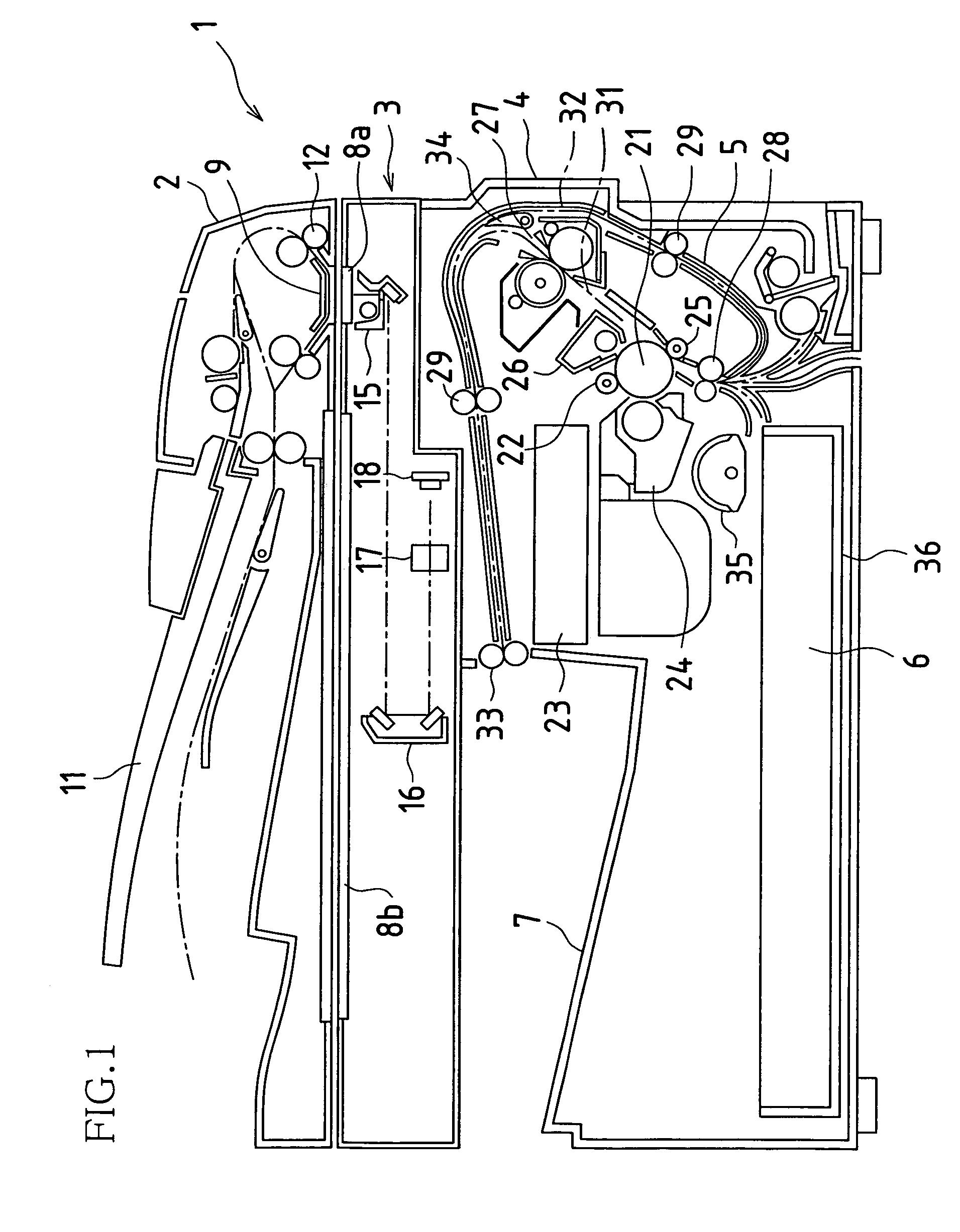
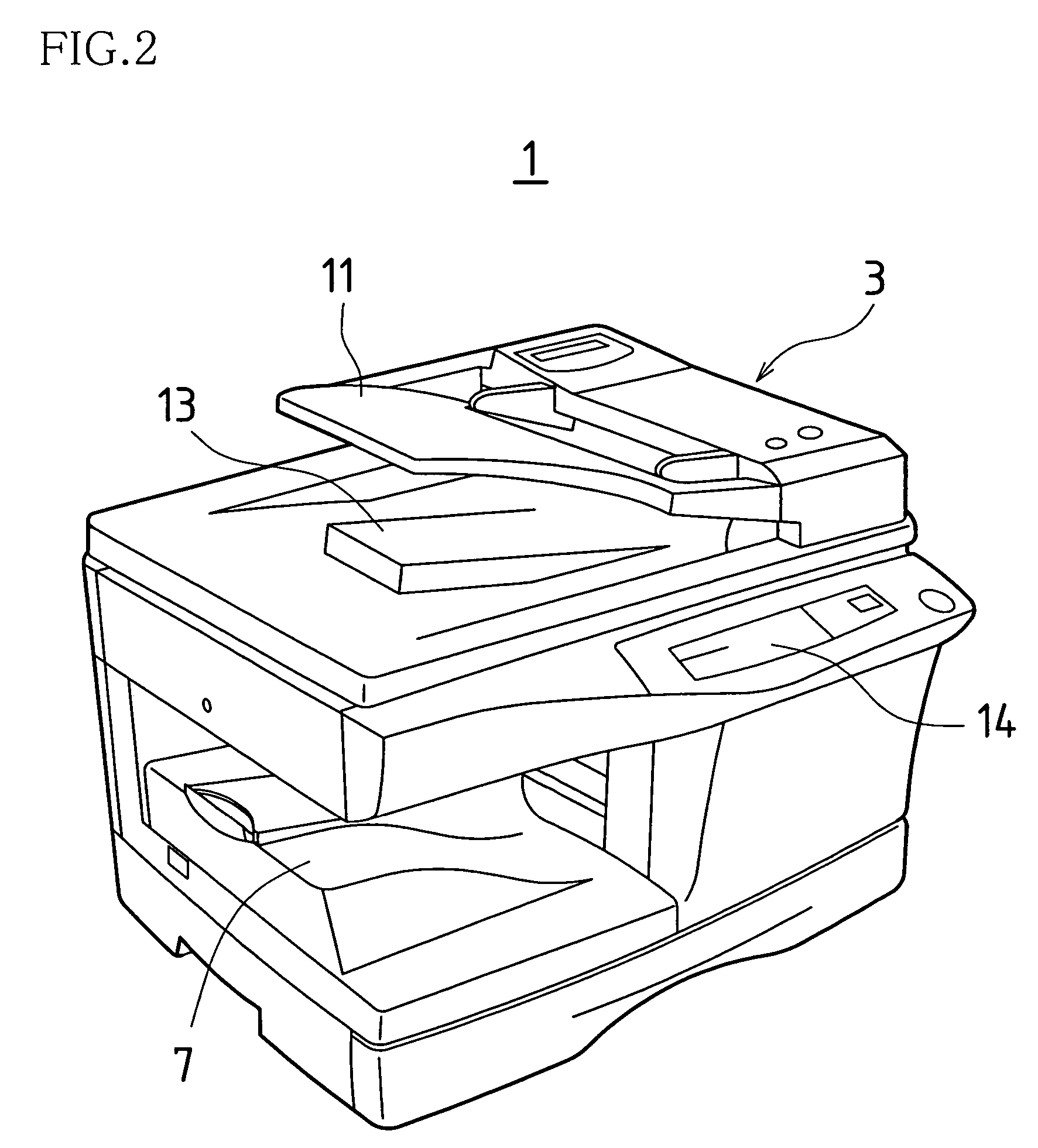
[0042]FIG. 1 is a side view showing an image forming apparatus to which one embodiment of a fixing device of the present invention is applied. FIG. 2 is a perspective view showing this image forming apparatus. The image forming apparatus 1 can perform selectively copy mode in which images in an original are read and printed on paper, facsimile mode in which images in an original are read and transmitted and images in an original are received and printed on paper, and printer mode in which images received through a network from an information terminal apparatus are printed on paper. The image forming apparatus 1 generally has a configuration including an original conveying portion 2, a reading portion 3, a printing portion 4, a paper conveying portion 5, a paper feed portion 6 and a paper discharge portion 7.

[0043]Next, the operation of the image forming apparatus 1 w...


PUM


Abstract

The present invention provides a fixing device for fixing a toner image formed on paper by sandwiching the paper in a nip region between a heating roller and a pressing roller and pressing the paper while heating the paper to a fixing temperature. This fixing device includes a cleaning roller that is in contact with the pressing roller, and temperature control means that sets a temperature of the heating roller to a cleaning temperature that is higher than the fixing temperature.

Description

BACKGROUND OF THE INVENTION[0001]This application claims priority under 35 U.S.C. § 119(a) on Patent Application No. 2005-10526 filed in Japan on Jan. 18, 2005, the entire contents of which are hereby incorporated by reference.[0002]The present invention relates to a fixing device that can be applied to electrophotographic or electrostatic recording image forming apparatuses or other types of image forming apparatuses.[0003]Conventionally, a fixing device of these types fixes a toner image formed on paper by sandwiching the paper in a nip region between a heating roller and a pressing roller so that the paper is pressed while being heated to fixing temperature, and is disclosed in, for example, JP S60-169876A (hereinafter, referred to as “Patent Document 1”). In Patent Document 1, a plurality of fixing conductions with varied fixing temperatures, pressing forces and the like are prepared, and an appropriate condition is selected among the fixing conditions, depending on the kind of ...

Claims


Application Information

Patent Timeline
Patent Type & Authority Patents(United States)
IPC IPC(8): G03G15/20
CPCG03G15/2025G03G15/2039
Inventor SUGITA, SHINJISHINKAWA, TATSUYAYAMANAKA, TAKASHIMUKAI, KANWAKAMOTO, KOUJI
Owner SHARP KK
Why Eureka
Try Eureka