Drive unit for compressor and refrigerator

a technology for compressors and drives, applied in the direction of refrigeration components, emergency protective arrangements for automatic disconnection, fluid pressure measurement by mechanical elements, etc., can solve the problems of compressor failure, sometimes performed in inadequate conditions, etc., and achieve low cost, simple arithmetic operation, and high reliability

Active Publication Date: 2008-06-24
DAIKIN IND LTD
View PDF20 Cites 29 Cited by
  • Summary
  • Abstract
  • Description
  • Claims
  • Application Information

AI Technical Summary

Benefits of technology

[0098]According to the thirteenth invention, it is predictable that an impact load such as shaft abnormalities or liquid compression has been imposed. Therefore, if such an impact load is predicted, the operating frequency of the compressor 1, for instance, will be reduced. As a result, operation is shifted into a more relaxed service condition, thereby avoiding severe damage.
[0099]According to the fourteenth invention, shaft abnormalities and liquid compression can be steadily predicted from the high frequency component of current. This makes it possible to avoid operation in an impact-load-imposed condition, thereby preventing a failure in the compressor 1 etc.
[0099]According to the fourteenth invention, shaft abnormalities and liquid compression can be steadily predicted from the high frequency component of current. This makes it possible to avoid operation in an impact-load-imposed condition, thereby preventing a failure in the compressor 1 etc.
[0099]According to the fourteenth invention, shaft abnormalities and liquid compression can be steadily predicted from the high frequency component of current. This makes it possible to avoid operation in an impact-load-imposed condition, thereby preventing a failure in the compressor 1 etc.
[0102]According to the seventeenth invention, since a reference value is set in accordance with the state of the refrigerant, the reliability of the predicted internal condition can be increased. This makes it possible to prevent a failure in the compressor 1 etc. without fail.
[0098]According to the thirteenth invention, it is predictable that an impact load such as shaft abnormalities or liquid compression has been imposed. Therefore, if such an impact load is predicted, the operating frequency of the compressor 1, for instance, will be reduced. As a result, operation is shifted into a more relaxed service condition, thereby avoiding severe damage.
[0109]According to the twenty-fourth invention, since the protective operation of the compressor 1 is carried out, a failure in the compressor 1 can be prevented, thereby achieving improved durability.
[0111]According to the twenty-sixth invention, since the compressor 1 is protected in preference to the control of the refrigerant circuit, improved durability can be achieved so that stable operation can be performed over the long period of time.
[0108]According to the twenty-third invention, since information on the internal condition of the compressor 1 is output, the user or the like can correctly grasp the internal condition.
[0109]According to the twenty-fourth invention, since the protective operation of the compressor 1 is carried out, a failure in the compressor 1 can be prevented, thereby achieving improved durability.
[0110]According to the twenty-fifth invention, since the protective operation is carried out by varying inverter control, a failure in the compressor 1 etc. can be prevented without fail.
[0111]According to the twenty-sixth invention, since the compressor 1 is protected in preference to the control of the refrigerant circuit, improved durability can be achieved so that stable operation can be performed over the long period of time.
[0116]According to the thirty-first invention, since forecast information is output, the user or the like can be notified of the failure forecast so that operation entailing a failure can be avoided.
[0071]According to the thirty-first invention, since information on the failure forecast can be sent to the outside, it is possible to inform the user or the like of the failure forecast so that an operation which leads to a failure can be avoided.
[0117]According to the thirty-second invention, since the contents of control etc. are changed, high-efficiency operation can be performed which leads to a reduction in the running cost.
[0118]According to the thirty-third invention, since the operating condition of the refrigerant circuit is predicted, abnormal operation and therefore a failure in the compressor 1 can be avoided without fail.
[0119]According to the thirty-fourth invention, since motor temperature can be estimated, there is no need to use a temperature detection sensor for the refrigerant circuit. In addition, in cases where data for predicting the rotating position of the motor 6 is used, a need to additional use of other components can be obviated. This makes it possible to obtain motor temperature at low cost. Further, once motor temperature is estimated, it becomes possible to determine from the estimated motor temperature whether the motor functions normally. If an abnormality is found, the operation is then stopped before the motor malfunctions, so that a failure can be avoided.
[0120]According to the thirty-fifth invention, the temperature of the magnets 1b can be estimated through simple arithmetic operation. The temperature of the magnets 1b can be used as motor temperature. Therefore, the predicted motor temperature has high reliability.
[0121]According to the thirty-sixth invention, motor temperature can be reliably estimated not by using a temperature sensor, but by utilizing a simple basic arithmetic expression.
[0122]According to the thirty-seventh invention, since a motor voltage equation for the steady state is obtained and the d-component of armature current in the motor voltage equation is set to zero at the time of the prediction, the number of operation elements as well as operation errors can be reduced. This enables high accuracy temperature estimation.
[0123]According to the thirty-eighth invention, since the estimated temperature is calibrated, improved reliability can be assured. This prevents the compressor 1 from being judged to be abnormal when it is operating in its normal state and, conversely, judged to be normal when it is operating in its abnormal state.
[0124]Additionally, the actual temperature used for the calibration is the temperature of the discharge pipe of the compressor 1. This discharge pipe temperature is used when performing discharge pipe temperature control of the refrigerant circuit, and the refrigerant circuit is equipped with a temperature sensor for detecting the temperature of the discharge pipe. Therefore, additional use of a temperature sensor is unnecessary for the calibration, which leads to cost reduction.

Problems solved by technology

In such refrigerant circuits, operation is sometimes performed in inadequate conditions owing to acceleration / deceleration of the compressor, abrupt fluctuations in load, and defective operation of other apparatus than the compressor.
If this happens, the compressor gets internal damage, resulting in a failure in the compressor.

Method used


Image

  • Drive unit for compressor and refrigerator
  • Drive unit for compressor and refrigerator
  • Drive unit for compressor and refrigerator

Examples


first embodiment

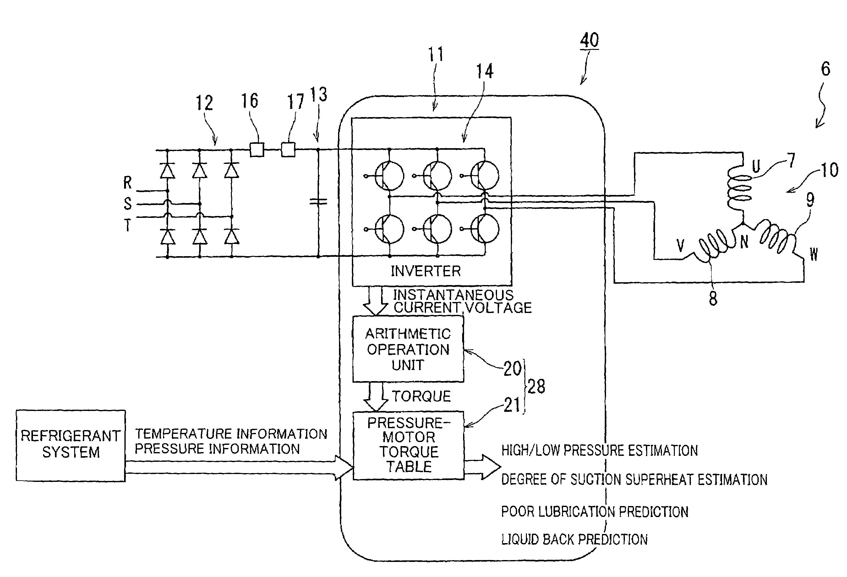
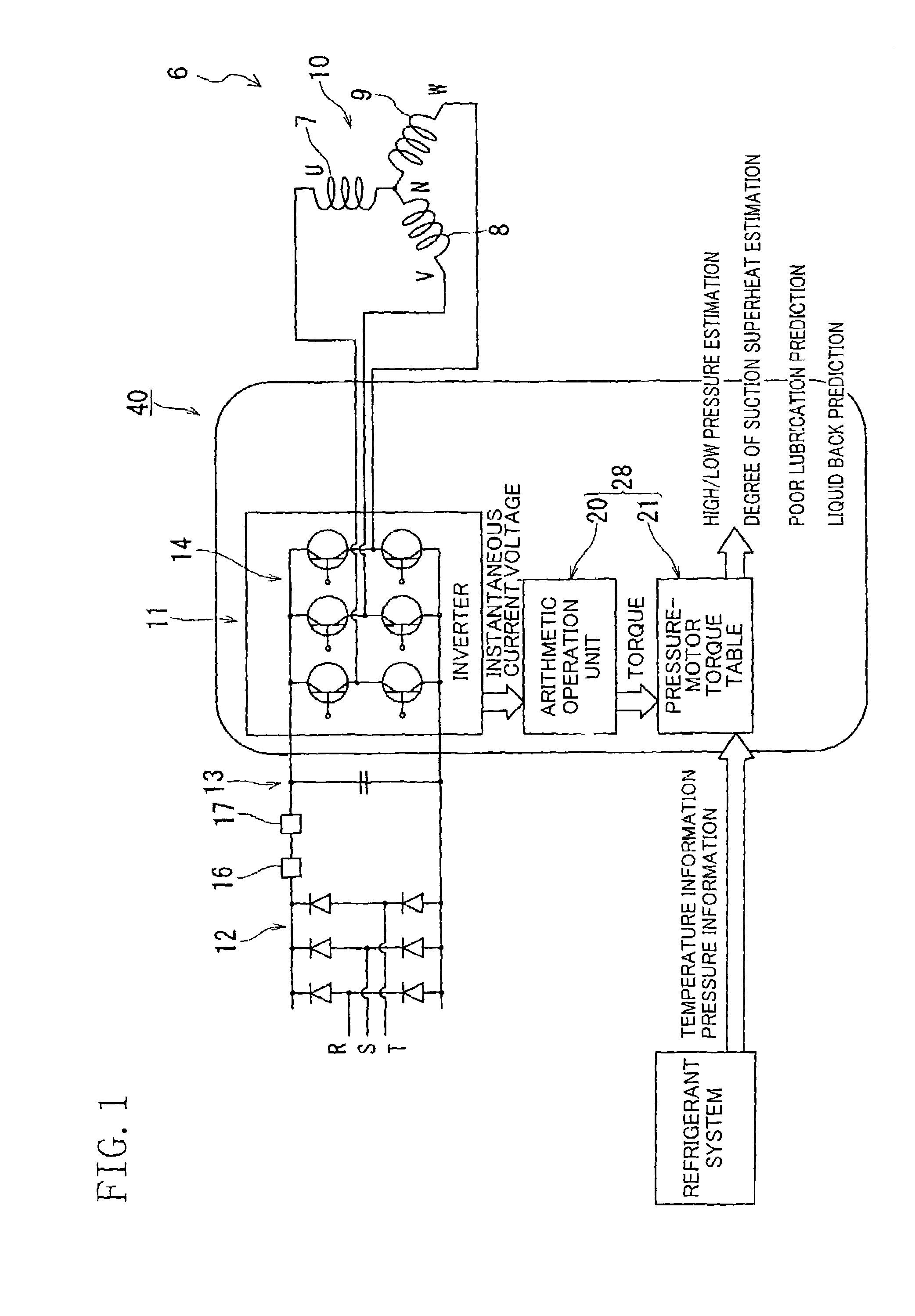
[0143]FIG. 1 schematically illustrates a drive unit 40 for a compressor 1, which has a prediction system (prediction means) 28 for predicting the internal condition of the compressor 1. The drive unit 40 for the compressor 1, which includes the prediction system 28, is used for the air conditioner (i.e., refrigerator) shown in FIG. 2.

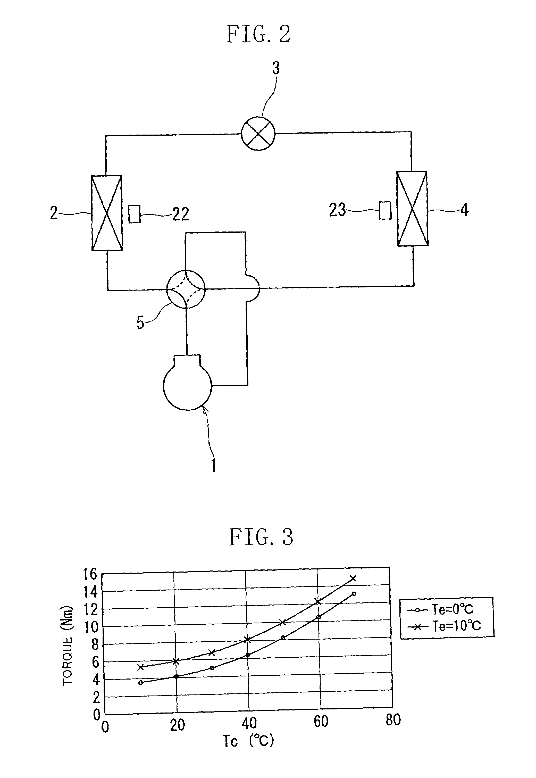
[0144]This air conditioner has a refrigerant circulation circuit (refrigerant system) which is a refrigerant circuit wherein the compressor 1, an outdoor heat exchanger 2, and an expansion valve (electric expansion valve) 3 and an indoor heat exchanger 4 are all connected in series. Cooling operation and heating operation are possible for the refrigerant circulation circuit by switching a four-way switching valve 5. The outdoor heat exchanger 2 and the indoor heat exchanger 4 are provided with temperature detecting means 22 and 23, respectively, to detect the refrigerant temperature of the heat exchangers 2 and 4. The temperature detecting means 22 and ...

second embodiment

[0209]Next, a second embodiment of the invention will be described with reference to the drawings. There will be explained only the parts of the second embodiment that differ from those of the first embodiment shown in FIG. 1. That is, in the second embodiment, the parts corresponding to those of FIG. 1 are identified by the same reference numerals and there will be omitted a detailed explanation thereof.

[0210]As shown in FIG. 11, a detecting means 15 is provided for the inverter section 14 in place of the current detector 16 and voltage detector 17 of the first embodiment. The detecting means 15 detects the current and voltage of the three-phase coil 10 of the brushless DC motor 6. The detecting means 15 has a current detecting section composed of a current detection sensor or the like capable of detecting current, and a voltage detecting section composed of a voltage detection sensor or the like capable of detecting voltage.

[0211]As shown in FIG. 13, the compressor 1 is made in th...


PUM

PropertyMeasurementUnit
condensation temperature Tcaaaaaaaaaa
currentaaaaaaaaaa

Abstract

An instantaneous current and instantaneous voltage of a three-phase coil of a brushless DC motor are detected, and the internal condition of a compressor is predicted from these detection values. The prediction about the internal condition of the compressor is made in such a way that motor driving torque which is a parameter of a motor model is identified and poor lubrication, liquid compression or the like is predicted from this identified motor driving torque. This enables it to make, in real time, a failure forecast, failure diagnosis etc. on the compressor.

Description

CROSS-REFERENCE TO RELATED APPLICATIONS[0001]This nonprovisional application claims priority under 35 U.S.C. §119(a) to Japanese Patent Application No. 2002-216025, filed in Japan on Jul. 25, 2002, and Japanese Patent Application No. 2002-367841, filed in Japan on Dec. 19, 2002, the entire contents of which are hereby incorporated by reference.TECHNICAL FIELD[0002]The present invention relates to a drive unit for a compressor and a refrigerator.BACKGROUND ART[0003]Generally, refrigerant circuits for use in an air conditioner are constituted by a compressor, an outdoor heat exchanger, an expansion valve and an indoor heat exchanger which are all connected in series to perform operation on the vapor-compression refrigerating cycle. In such refrigerant circuits, operation is sometimes performed in inadequate conditions owing to acceleration / deceleration of the compressor, abrupt fluctuations in load, and defective operation of other apparatus than the compressor. If this happens, the c...

Claims


Application Information

Patent Timeline
Patent Type & Authority Patents(United States)
IPC IPC(8): G01L3/00G06F11/30G06F19/00F25B49/02F04B49/02F04B49/06F04B49/10F24F11/02F24F11/38F24F11/46F24F11/49F24F11/59F24F11/64F24F11/86F24F11/88F24F11/89F24F140/00F24F140/20F25B1/04F25B13/00F25B49/00
CPCF04B49/065F25B49/005F25B49/025H02P21/13H02P29/0033H02P29/02F04B49/10F25B2700/2117F04B2203/0201F04B2203/0202F25B1/04F25B13/00F25B2500/16F25B2500/19F25B2600/021F25B2700/151Y02B30/741F25B2700/2116F04C2270/80F04C2270/86H02P29/40Y02B30/70H02P6/12F25B49/02
Inventor HIKAWA, TAKESHIMAEDA, TOSHIYUKIKASAHARA, SHINICHIYAMAGUCHI, TAKAHIROIZUMI, SHIGENOBUKOIZUMI, KIYOSHIKITA, MASANOBU
Owner DAIKIN IND LTD
Why Eureka
Try Eureka