
Emulation system with peripherals recording emulation frame when stop generated

a technology of emulation system and peripheral, which is applied in the field of complex integrated circuits, can solve the problems of complex testing of programmable digital processors such as microprocessors and digital signal processors, and increasing the difficulty of testing such integrated circuits

Inactive Publication Date: 2008-06-24
TEXAS INSTR INC
View PDF8 Cites 31 Cited by
  • Summary
  • Abstract
  • Description
  • Claims
  • Application Information

AI Technical Summary

Benefits of technology

Facilitates easier testing and emulation of complex integrated circuits by providing visibility into programmable digital processor behavior, allowing for precise control and monitoring of debug events and interrupts, thereby simplifying the debugging process.

Problems solved by technology

Programmable digital processors such as microprocessors and digital signal processors have become very complex machines.
Testing these programmable digital processors has also become complex task.
Even so, the number of logic circuits and their complex relationships makes testing such integrated circuits an increasingly difficult task.
A trend in electronics makes this testing problem more difficult.
Because the address and data busses of the digital processor are no longer brought out the device pins, it is more difficult to determine the behavior of the embedded processor from external connections.
Another trend in electronics makes this testing problem more difficult.
Thus there may be more than one programmable digital processor on a single integrated circuit, each having limited visibility via the device pins.
Another problem is product emulation when employing these programmable digital processors.

Method used


Image

  • Emulation system with peripherals recording emulation frame when stop generated
  • Emulation system with peripherals recording emulation frame when stop generated
  • Emulation system with peripherals recording emulation frame when stop generated

Examples


Embodiment Construction

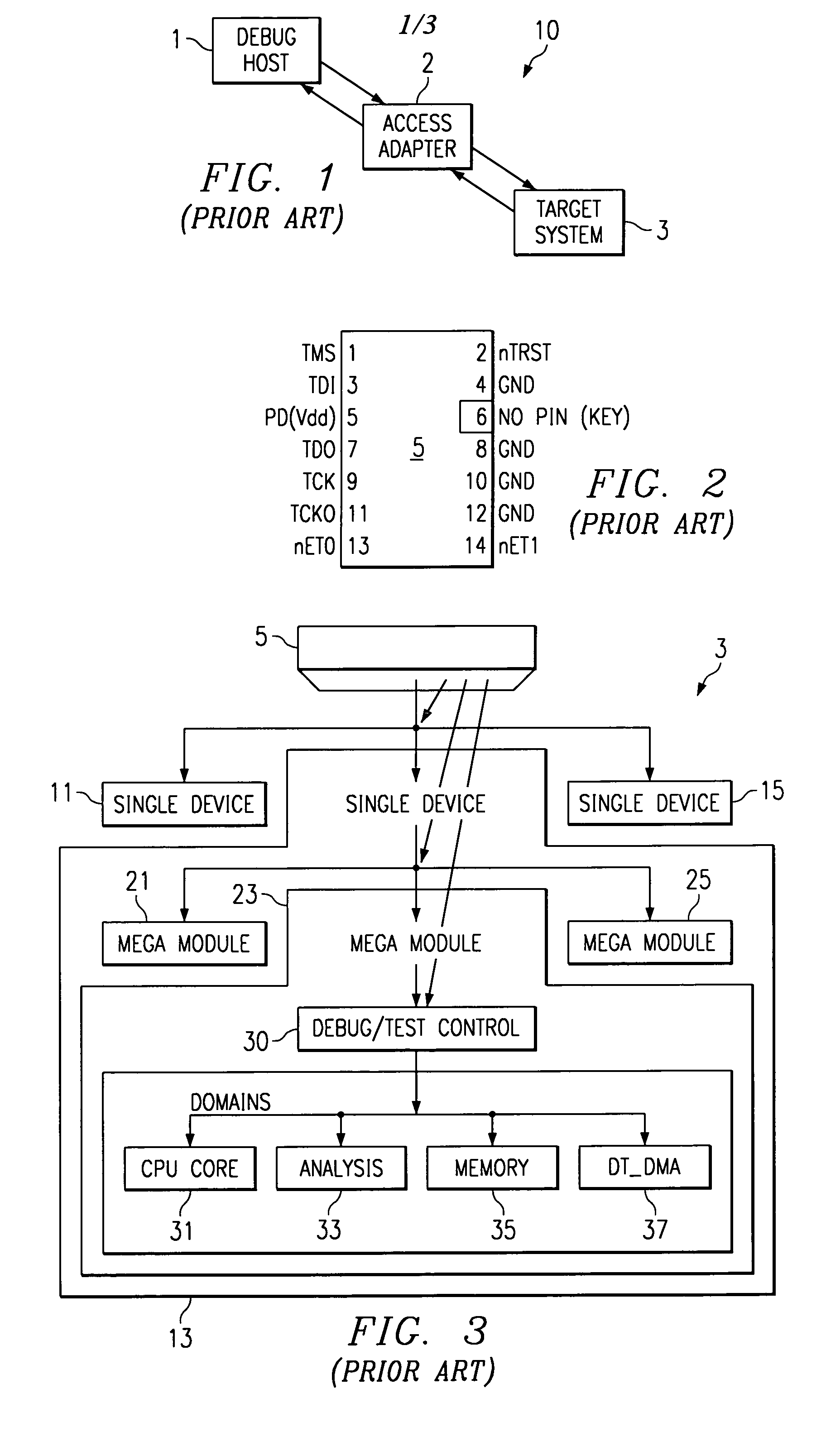
[0029]FIG. 1 illustrates the environment of the debugging system of this invention. This environment connects high level debugging software executing on a debug host computer 1 to a low level debug interface supported by the target system 3. In this invention the target system 3 may include more than one programmable digital processor and possibly more than one such programmable digital processor on a single integrated circuit. In this application the term programmable digital processor is meant to encompass devices commonly known as microprocessors, microcontrollers and digital signal processors. The target system 3 provides a standard interface to the access adapter 2.

[0030]Debug host computer 1 consists of a computer, for example a PC, running a CPU core specific software debugger as one of its tasks. The debug host computer 1 allows the user to issue high level commands such as setting breakpoint, single stepping the programmable digital processor in target system 3 and displayi...


PUM


Abstract

In-circuit-emulation of an integrated circuit includes a digital data processor capable of executing program instructions. A first debug event is detected during normal program execution. The causes the in-circuit-emulation to suspend program execution except for real time interrupts. A debug frame counter increments on each interrupt and decrements on each return from interrupt. If a debug event is detected during an interrupt service routine, that interrupt service routine is suspended and the count of the debug frame counter is stored. Execution of other interrupt service routines in response to corresponding interrupts is still permitted. The integrated circuit includes plural debug event detectors and the debug frame count is stored at the detector detecting a debug event during an interrupt service routine. This permits a determination of the order of interrupts triggering debug events by reading the stored debug frame count from each debug event detector.

Description

CLAIM OF PRIORITY[0001]This application is a continuation-in-part of U.S. patent application Ser. No. 09 / 481,853 filed Jan. 14, 2000 now abandoned, which claims priority under 35 USC §119(e)(1) of Provisional Application No. 60 / 120,810, filed Feb. 19, 1999.CITATION OF RELATED APPLICATIONS[0002]This application is related to co-assigned applications:[0003]Ser. No. 09 / 154,385 entitled “METHOD OF INITIALIZING A CPU CORE FOR EMULATION” filed Sep. 16, 1998, now U.S. Pat. No. 6,167,385 issued Dec. 26, 2000; and[0004]The following contemporaneously filed applications:[0005]Ser. No. 09 / 483,367, entitled “EMULATION SUSPEND MODE WITH DIFFERING RESPONSE TO DIFFERING CLASSES OF INTERRUPTS” claiming priority from U.S. Provisional Application No. 60 / 120,809 filed Feb. 19, 1999, now U.S. Pat. No. 6,553,513;[0006]Ser. No. 09 / 481,852, entitled “EMULATION SUSPENSION MODE WITH STOP MODE EXTENSION” claiming priority from U.S. Provisional Application No. 60 / 120,809 filed Feb. 19, 1999, now U.S. Pat. No....

Claims


Application Information

Patent Timeline
Patent Type & Authority Patents(United States)
IPC IPC(8): G06F11/00G06F11/36
CPCG06F11/3656
Inventor SWOBODA, GARY L.
Owner TEXAS INSTR INC
Learn More