
Process for guiding printing media and printing media guide

a printing media and guide technology, applied in the direction of pile separation, transportation and packaging, article separation, etc., can solve the problems of reducing print quality, unfavorable movement of edges, and fluttering or bending edges in undesirable ways, so as to prevent undesirable movement of edges

Inactive Publication Date: 2008-07-01
EASTMAN KODAK CO
View PDF26 Cites 2 Cited by
  • Summary
  • Abstract
  • Description
  • Claims
  • Application Information

AI Technical Summary

Benefits of technology

This solution effectively prevents undesirable edge movements, ensuring stable edge guidance and preventing print quality issues, allowing for smooth conveyance through mechanisms like microwave systems without edge contact, maintaining image quality.

Problems solved by technology

If the printing medium is conveyed such that the edges do not make contact, undesirable movements of the edges can occur.
The edge can begin to flutter or become bent in an undesirable way; it can, in particular, hang down or roll up, or the like.
The undesirable movements can cause reductions in print quality.
The layer of toner can be adversely affected or, inside a lithographic or ink jet printing machine, ink that has not yet dried can run.
If the path of travel runs through another mechanism, the movements of the edges of the printing medium can result in the medium making contact with or bumping into feed-in slots that are present.
This can damage the printing medium, or cause a paper jam.

Method used


Image

  • Process for guiding printing media and printing media guide
  • Process for guiding printing media and printing media guide
  • Process for guiding printing media and printing media guide

Examples


Embodiment Construction

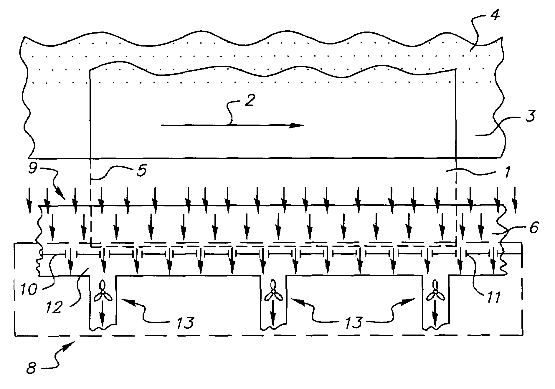
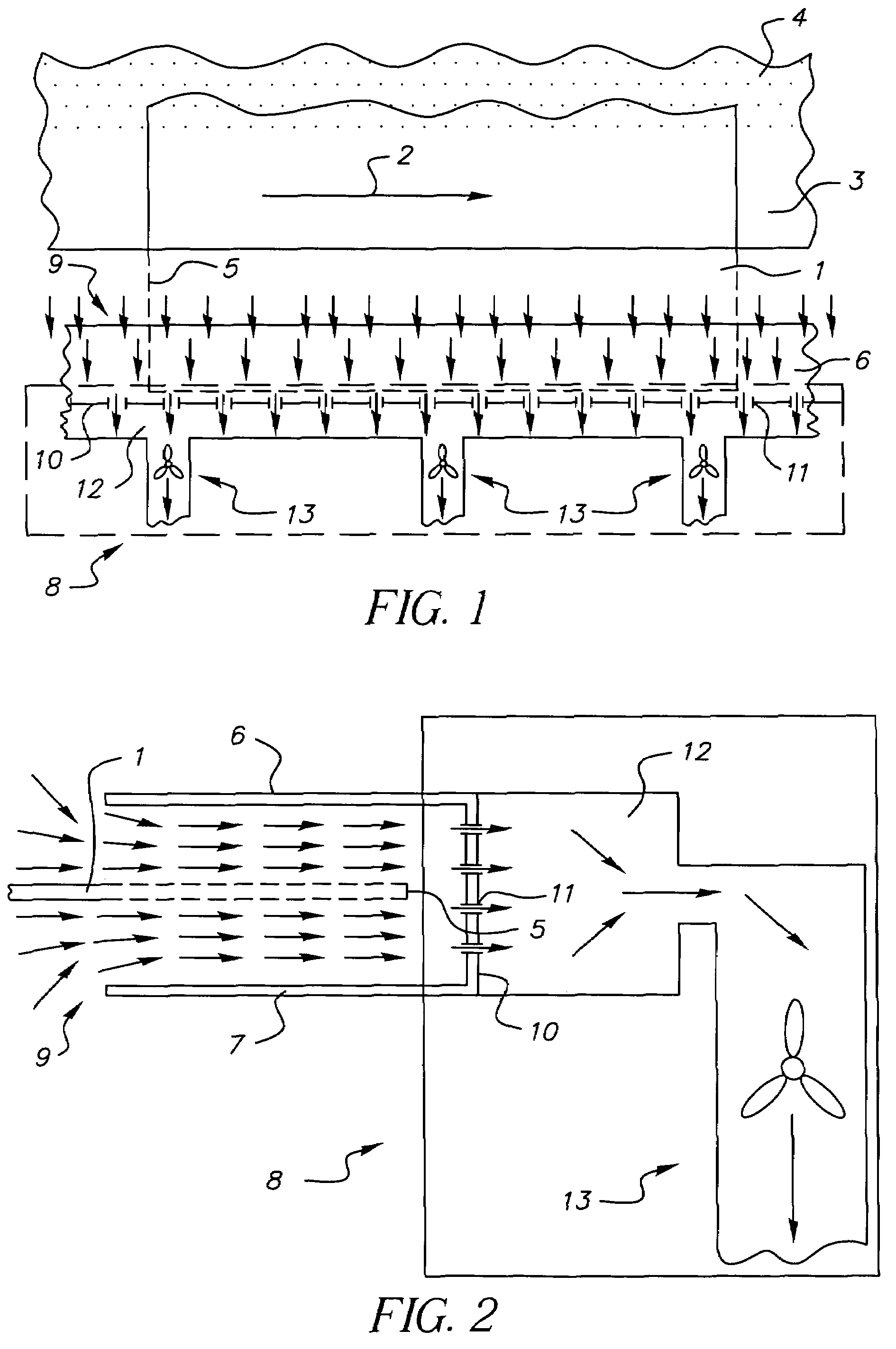
[0026]FIG. 1 shows a printing media guide according to the invention. The view is from overhead. A printing medium 1 is being conveyed on a conveyor path in the direction of arrow 2. Impetus for the movement is transferred to the printing medium 1 via a conveyor belt 3. In principle, the printing medium 1 can be held on the conveyor belt 3 in various ways, for example, by electrostatic energy. With respect to the conveyor belt 3 shown here, the printing medium 1 is held to the conveyor belt 3 by vacuum induced through suction holes 4.

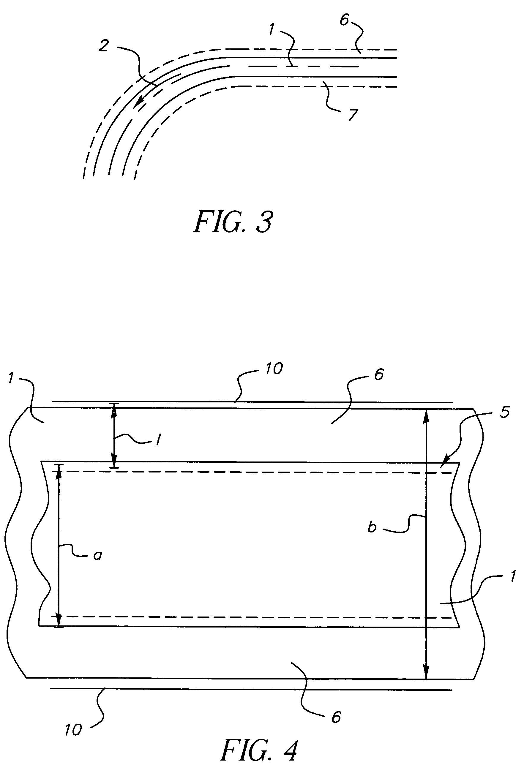
[0027]An edge area 5 of the printing medium shown by the dashed lines, also referred to hereinafter as edge 5 or printing medium edge 5, is located in the vicinity of air guide elements 6 and 7. In the overhead view shown here, only the upper air guide element 6 is visible. In FIG. 2, both air guide elements 6 and 7 can be seen. The air guide elements 6 and 7 connect to an air suction mechanism 8. A cross section of the air suction mechanism 8 is shown ...


PUM


Abstract

Guiding a printing medium that is being conveyed along a travel path in a printing machine, whereby the printing medium is not making contact along at least one edge. A stream of sucked air (9) is directed at least partially outward, with respect to at least one edge (5) of the printing medium. A printing media guide with at least one air suction mechanism (8) for sucking air out of the area of the travel path of the printing medium (1) in order to create a suction air stream (9) is directed at least partially outwards.

Description

FIELD OF THE INVENTION[0001]The invention relates in general to guiding a printing medium that is being conveyed along a travel path in a printing machine, whereby the printing medium is not making contact along at least one edge.BACKGROUND OF THE INVENTION[0002]In printing machines, especially in electrophotographic printing machines, printing media such as paper, for example, are conveyed along a path of travel with the aid of conveyor belts, traction systems, or the like.[0003]Printing media can be conveyed such that only certain areas of the printing media come into contact with the appropriate conveying elements. For example, the printing medium can lie midway on an electrostatic conveyor belt and be conveyed thereby while one edge or even both edges of the printing medium make no contact.[0004]This freedom of contact of the edges can, for example, be necessary when microwave fuser mechanisms are used, as is proposed in DE 101 45 005 A1. In such case, for example, toner can ini...

Claims


Application Information

Patent Timeline
Patent Type & Authority Patents(United States)
IPC IPC(8): B65H5/00B41F13/02B65H5/22B65H5/38B65H29/52
CPCB65H5/38B65H29/52B65H2701/132B65H2406/352B65H2406/111
Inventor ROHDE, DOMINGOSEIMETZ, LARS
Owner EASTMAN KODAK CO
Learn More