Hydraulic control system for a variable compression ratio internal combustion engine
- Summary
- Abstract
- Description
- Claims
- Application Information
AI Technical Summary
Benefits of technology
Problems solved by technology
Method used
Image
Examples
Embodiment Construction
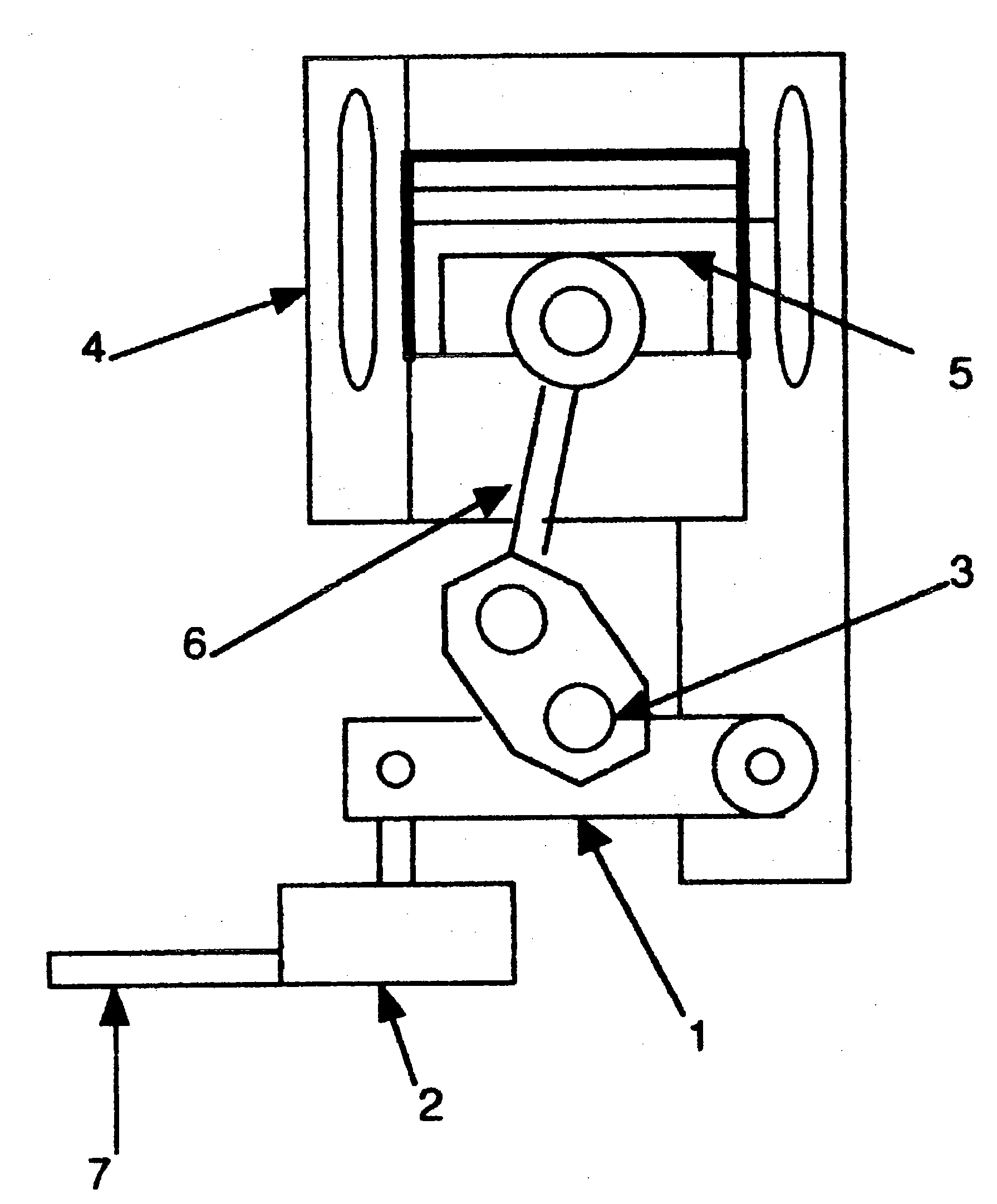
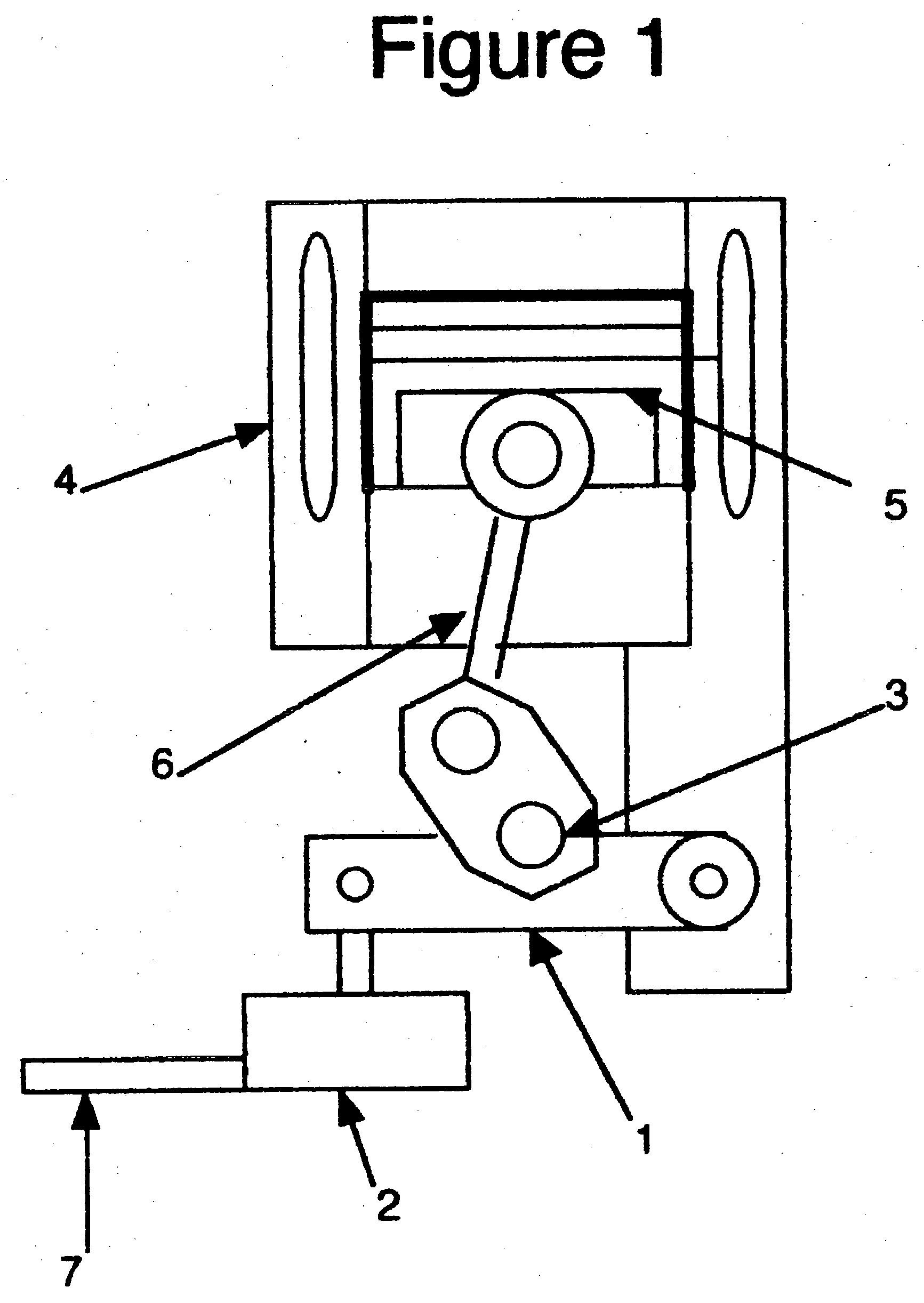
[0013] Referring to FIG. 1, an engine block 4, pistons 5, connecting rod 6, crankshaft 3, hinged moveable crankshaft assembly 1, hydraulic positioning device 2 and hydraulic tubing 7 leading to constant pressure hydraulic reservoir.
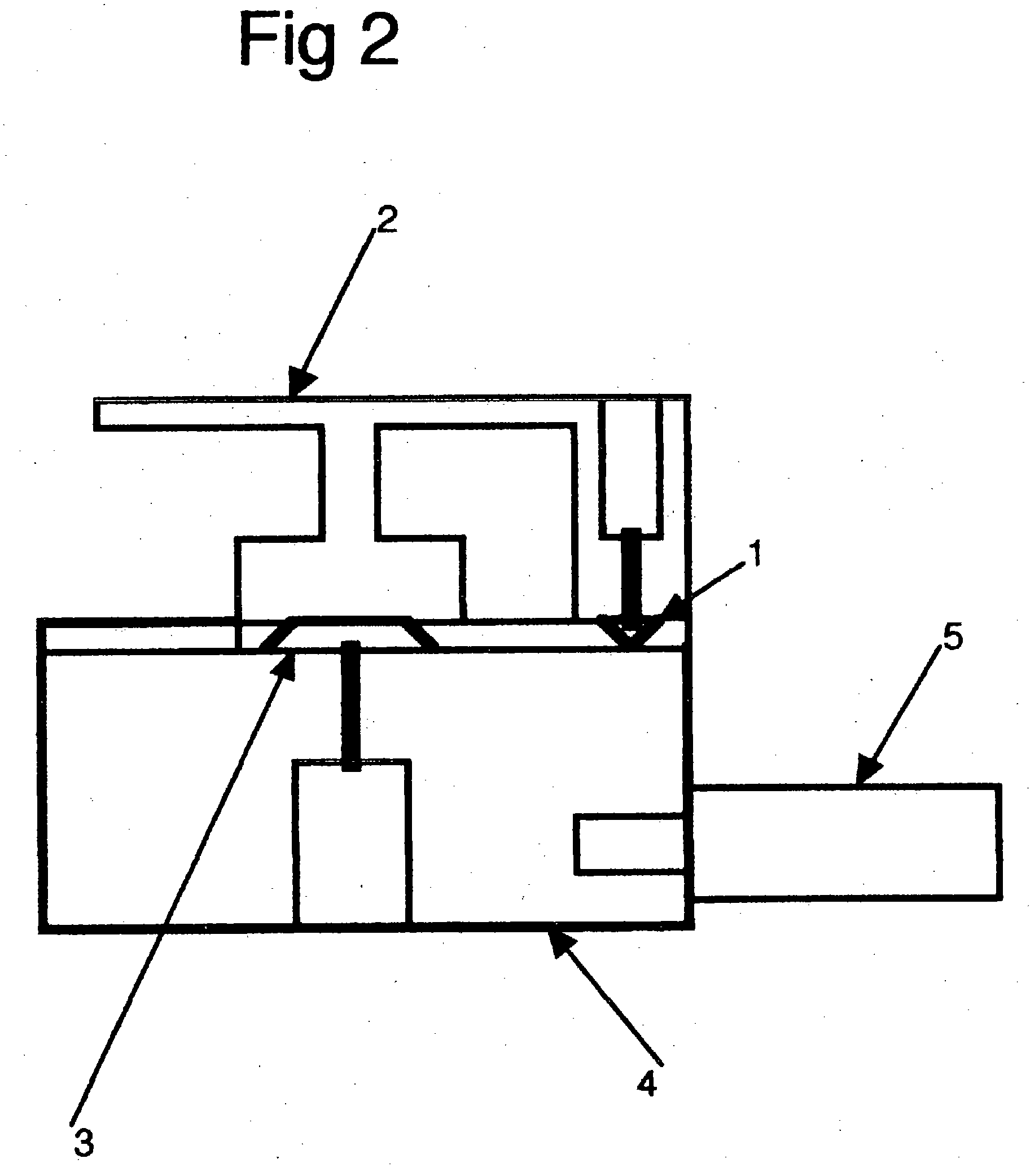
[0014] Referring to FIG. 2, the hydraulic fluid constant pressure reservoir 4, spring-loaded piston to maintain desired hydraulic pressure 5, pressure relief valve 3 allows fluid to pass from thehydraulic positioning device to the hydraulic fluid reservoir, pressure relief 1 valve 1 allows fluid to flow from the reservoir to the hydraulic positioning device. Tubing 2 connects the hydraulic reservoir with the hydraulic positioning device.
[0015] Referring to FIG. 3, a pressure versus volume plot for a cycle at full power and design compression ratio of 7:1.
[0016] Referring to FIG. 4, a pressure versus volume plot for a cycle at 34% power and design compression ratio of 7:1.
[0017] Referring to FIG. 5, a pressure versus volume plot for a cycle at 34% powe...
PUM
 Abstract
Description
Claims
Application Information
 - R&D
- Intellectual Property
- Life Sciences
- Materials
- Tech Scout
- Unparalleled Data Quality
- Higher Quality Content
- 60% Fewer Hallucinations
Browse by: Latest US Patents, China's latest patents, Technical Efficacy Thesaurus, Application Domain, Technology Topic, Popular Technical Reports.
© 2025 PatSnap. All rights reserved.Legal|Privacy policy|Modern Slavery Act Transparency Statement|Sitemap|About US| Contact US: help@patsnap.com


