
Conveyor device for the conveyance of workpieces, specifically of circuit boards, in the conveyance direction along a conveyance path

Active Publication Date: 2016-01-12
VISCOM
View PDF10 Cites 1 Cited by
  • Summary
  • Abstract
  • Description
  • Claims
  • Application Information

AI Technical Summary

Benefits of technology

The invention aims to prevent collisions between workpieces and increase conveyance rate by rejecting a redundant design of conveyance paths. Additionally, a refinement is introduced to prevent collisions by adding an actuator with a hoisting / lowering device for a spacer. This device is responsible for lifting the spacer in the active mode to achieve minimum spacing between workpieces and lowering it back to its starting position when the conveyance reaches the endpoint.

Problems solved by technology

However, the known conveyance devices of the stated kind present the inherent disadvantage that a deviation in the conveyance speeds of workpiece conveyance in the primary and secondary conveyance means will mean that either the geometric spacing between the workpieces in the conveyance direction becomes unreasonably large, or the workpieces may collide with each other and be damaged, especially in the transition region between first and second partial path.
In this respect the known conveyance devices of the stated kind present the disadvantage of a lower workplace conveyance rate or the disadvantage of a high rejection rate for workpieces.
The disadvantages mentioned result in loss of economical operation of a corresponding conveyance device.

Method used


Image

  • Conveyor device for the conveyance of workpieces, specifically of circuit boards, in the conveyance direction along a conveyance path
  • Conveyor device for the conveyance of workpieces, specifically of circuit boards, in the conveyance direction along a conveyance path
  • Conveyor device for the conveyance of workpieces, specifically of circuit boards, in the conveyance direction along a conveyance path

Examples


Embodiment Construction

[0072]The same or corresponding components / constituents or elements are indicated in the figures by the same reference numbers. For reasons of enhanced viewing, not all reference numbers are always entered in the figures. A correspondence between the relevant components / constituents or elements, however, is indicated by the same mode of representation or by a depiction corresponding to the particular view.

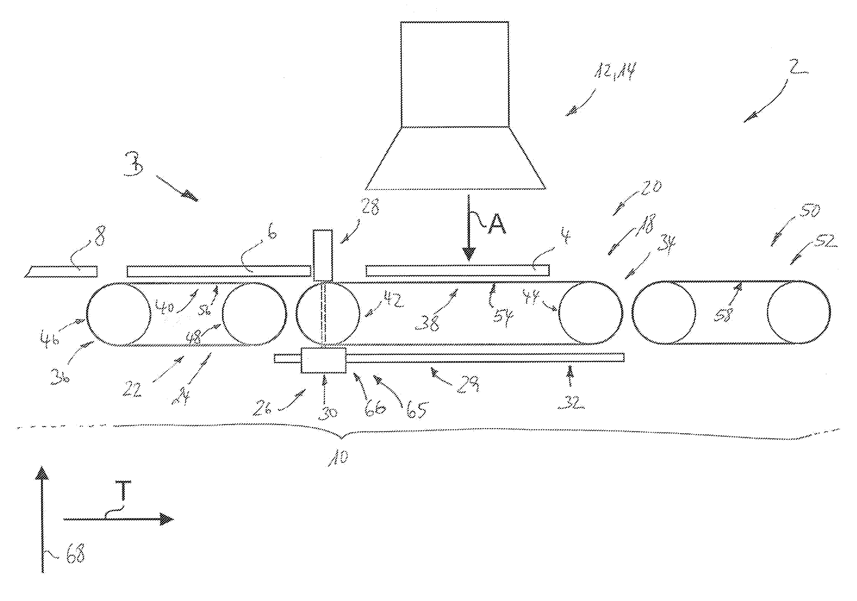
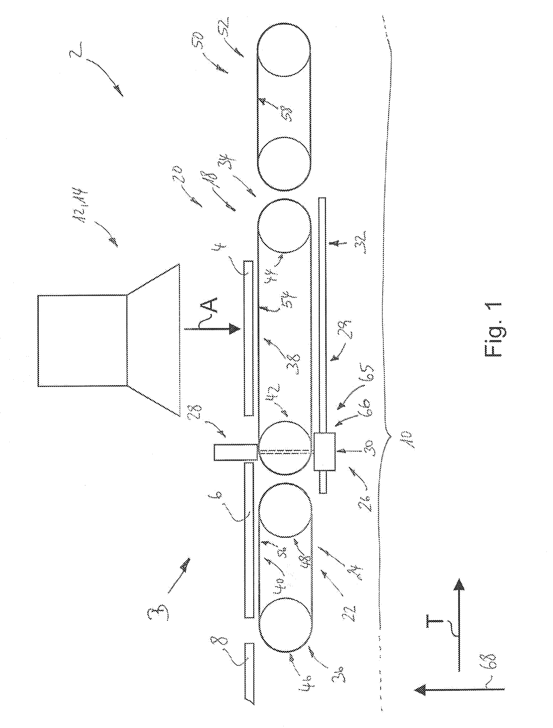
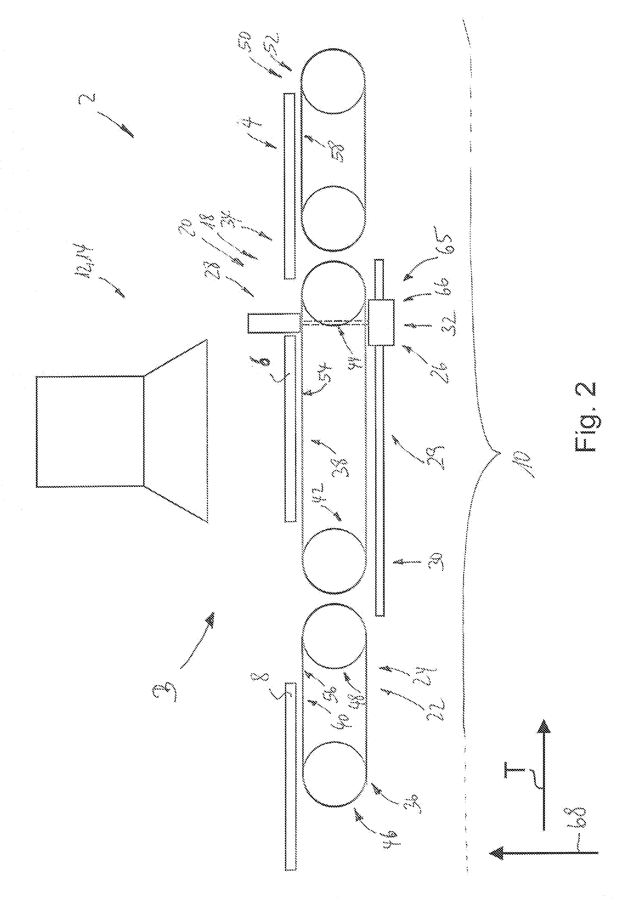
[0073]FIG. 1 shows one embodiment of a conveyance device 2 with the invention (hereinafter also abbreviated as conveyance device 2) for conveyance of workpieces 4, 6, 8, specifically of circuit boards, in the conveyance direction T along a conveyance path 10.

[0074]The conveyance device 2 or the conveyance path 10 is a constituent of a production line (not depicted) and thus feeds the particular workpieces 2, 4, 6 to the processing stations 12 for processing.

[0075]With the invention, a processing station 12 also encompasses the functions of a test station 14 for workpiece testing.

[0...


PUM


Abstract

A conveyor device for the conveying workpieces, specifically circuit boards. The conveyor device is equipped with a primary and secondary conveyance for conveying the workpiece along a first or second partial path of the conveyance path. Workpieces are fed to the first partial path via the second partial path. Separators operate along the first partial path to separate one workpiece from a trailing workpiece. The Separators feature at least one spacer which can be moved and displaced by a control. After the workpiece passes the starting position, the spacer switches into an active mode, in which it is placed behind the workpiece and tracks it, thereby forming a minimum spacing between the workpiece and the trailing workpiece, and upon reaching the ending position, the spacer switches into an inactive mode, in which the spacer returns to the starting position.

Description

CROSS-REFERENCE TO RELATED APPLICATIONS[0001]This application claims priority to German application number 10 2013 112 056.3 filed Oct. 31, 2013, and to European application number EP13005442 filed Nov. 20, 2013, both of which are entirely incorporated herein by reference.FIELD OF THE INVENTION[0002]The invention relates to a conveyor device for the conveyance of workplaces, specifically of circuit boards, in the conveyance direction along a conveyance path.BACKGROUND OF THE INVENTION[0003]Conveyor devices of the stated kind are used for different purposes and in different industries. For example, conveyor devices are used within a manufacturing line to convey workplaces from one processing station to another processing station. The conveyance path in a particular conveyor device in this activity is subdivided into partial paths, to which conveyance means are assigned, in order to convey a workplace in the conveyance direction along the partial path.[0004]Conveyor devices of the sta...

Claims


Application Information

Patent Timeline
IPC IPC(8): B65G47/26B65G47/29H01L21/677B65G47/30B65G15/22
CPCB65G47/30B65G15/22B65G47/29H01L21/6776H01L21/67706H05K13/0061
Inventor HEUSER, MARTIN
Owner VISCOM
Learn More