
Medical Imaging Device

Inactive Publication Date: 2012-02-23
SIEMENS HEALTHCARE GMBH
View PDF14 Cites 0 Cited by
  • Summary
  • Abstract
  • Description
  • Claims
  • Application Information

AI Technical Summary

Benefits of technology

[0008]It is proposed that the medical imaging device should have a film disposed on the wall at least partially enclosing the receiving region, said film generating at least one virtual image. The medical imaging device is advantageously formed by a magnetic resonance device or a computed tomography device. In this context a virtual image refers in particular to a visual mapping of a light-reflecting object and / or an illuminated object, which in contrast to a real image cannot be displayed on a screen. The light-reflecting and / or illuminated object here is disposed between a focal point of at least one lens and the at least one lens. The inventive embodiment allows a depth effect of the receiving region to be suggested to the patient inside the receiving region, in that a greater, virtual distance between the patient on the patient couch and the wall with the film disposed on it than the actual distance between the patient and the wall can be suggested to and / or simulated for said patient. For patients with a tendency to claustrophobic anxiety states in particular this can induce a feeling of well being and / or at least partially suppress any claustrophobic anxiety states as a result of a suggested and / or simulated depth effect of the film. A depth and / or thickness of film suggested to the patient is at least twenty times the structurally required depth and / or thickness of film and particularly advantageously at least thirty times the structurally required depth and / or thickness of film, so that the film produces a three-dimensional impression and / or effect for the patient. The film has a thickness of approx. 0.5 mm to 0.6 mm, the depth effect being up to 20 mm or the virtual image being disposed at a virtual distance of up to 20 mm in particular from the viewpoint of the patient or a viewer behind the surface of the film. This depth effect can be achieved particularly economically inside the receiving region by using a film. The film also allows a patient to concentrate and / or focus his / her eyes and / or attention on the film during a measurement, which can help the patient relax significantly during an imaging measurement, thereby preventing unnecessary and in particular undesirable movement of the patient.
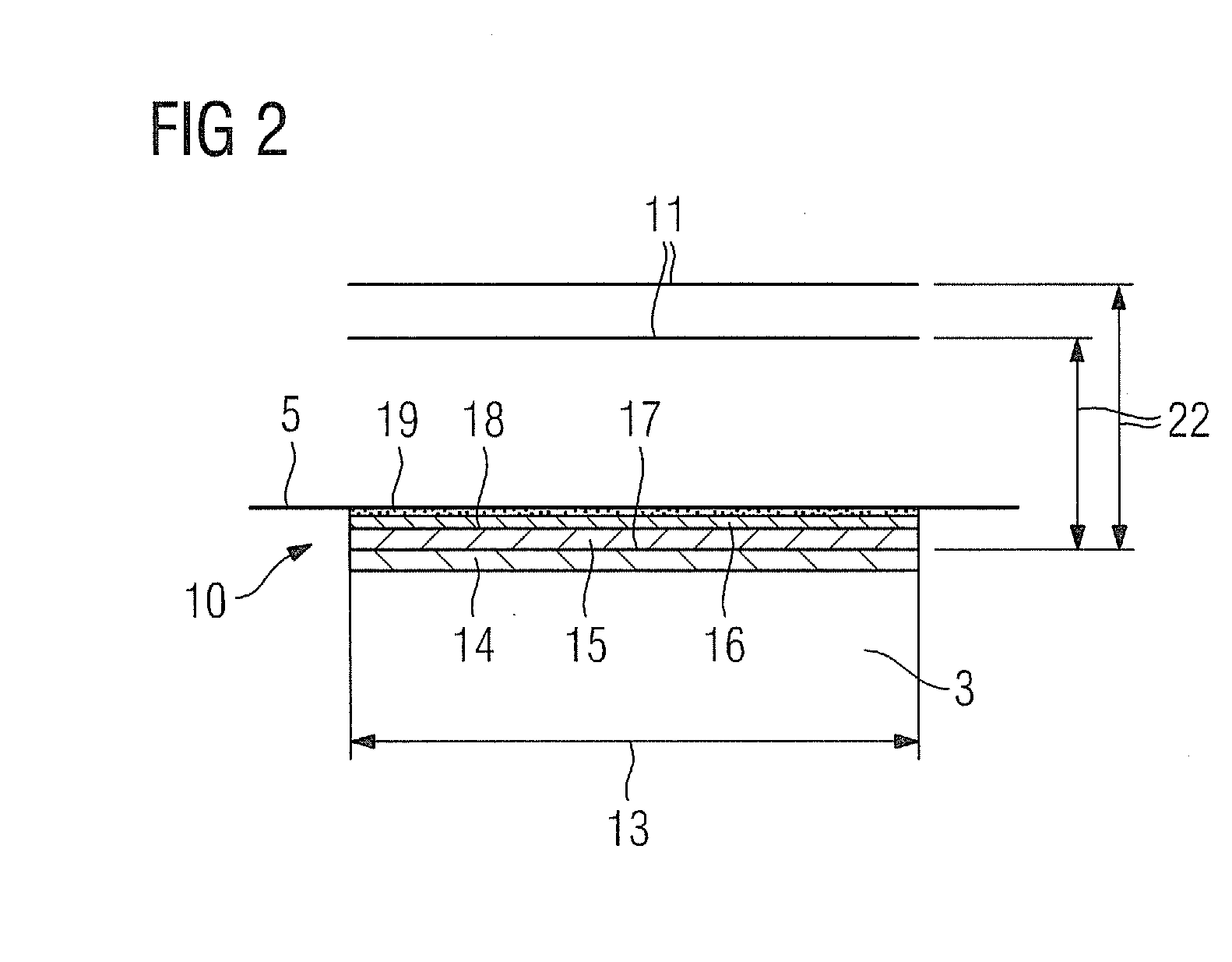
[0009]It is also proposed that the film should comprise at least two layers, thereby allowing the depth effect or virtual image to be generated in a structurally simple and space-saving manner by means of the film. It is particularly advantageous here for the film to have at least one layer, which comprises a plurality of optical lens elements, thereby allowing a sharp, undistorted image to be generated when the film is viewed from any direction. The layer with the plurality of optical lens elements is preferably formed by a top layer, which is disposed on a side of the film facing the patient. The optical lens elements are preferably formed by convex lens elements, the diameter of the individual convex lens elements being a multiple smaller than the thickness of the film.

Problems solved by technology

The distance between the face and / or eye region of the patient and a wall of the medical imaging device enclosing the receiving region is therefore maximum 25 cm to 30 cm, which can cause many patients to experience feelings of claustrophobia and / or unease.
However this mirror must also be configured to be magnetic-resonance-compatible for deployment in a magnetic resonance device, which makes the production of the mirror expensive.
Also the mirror takes up a lot of space inside the receiving region and can therefore cause the patient to be impeded and / or at least restricted inside the receiving region.
However because of its proximity to the patient this adhesive strip can cause the patient to feel ill at ease by placing an excessive strain on the eye muscles of the patient.

Method used


Image

  • Medical Imaging Device
  • Medical Imaging Device
  • Medical Imaging Device

Examples


Embodiment Construction

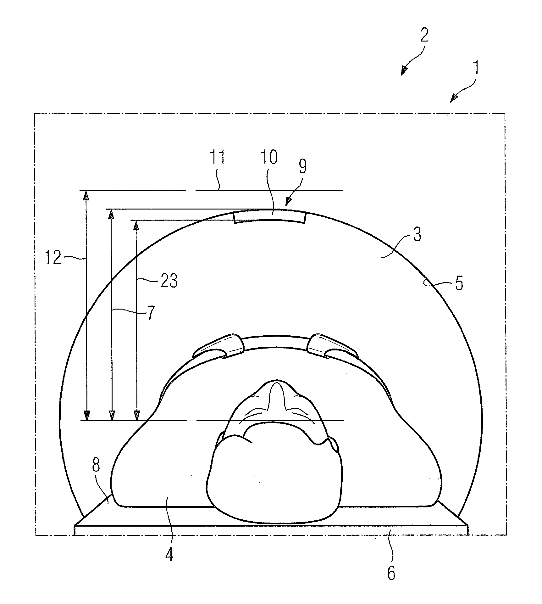
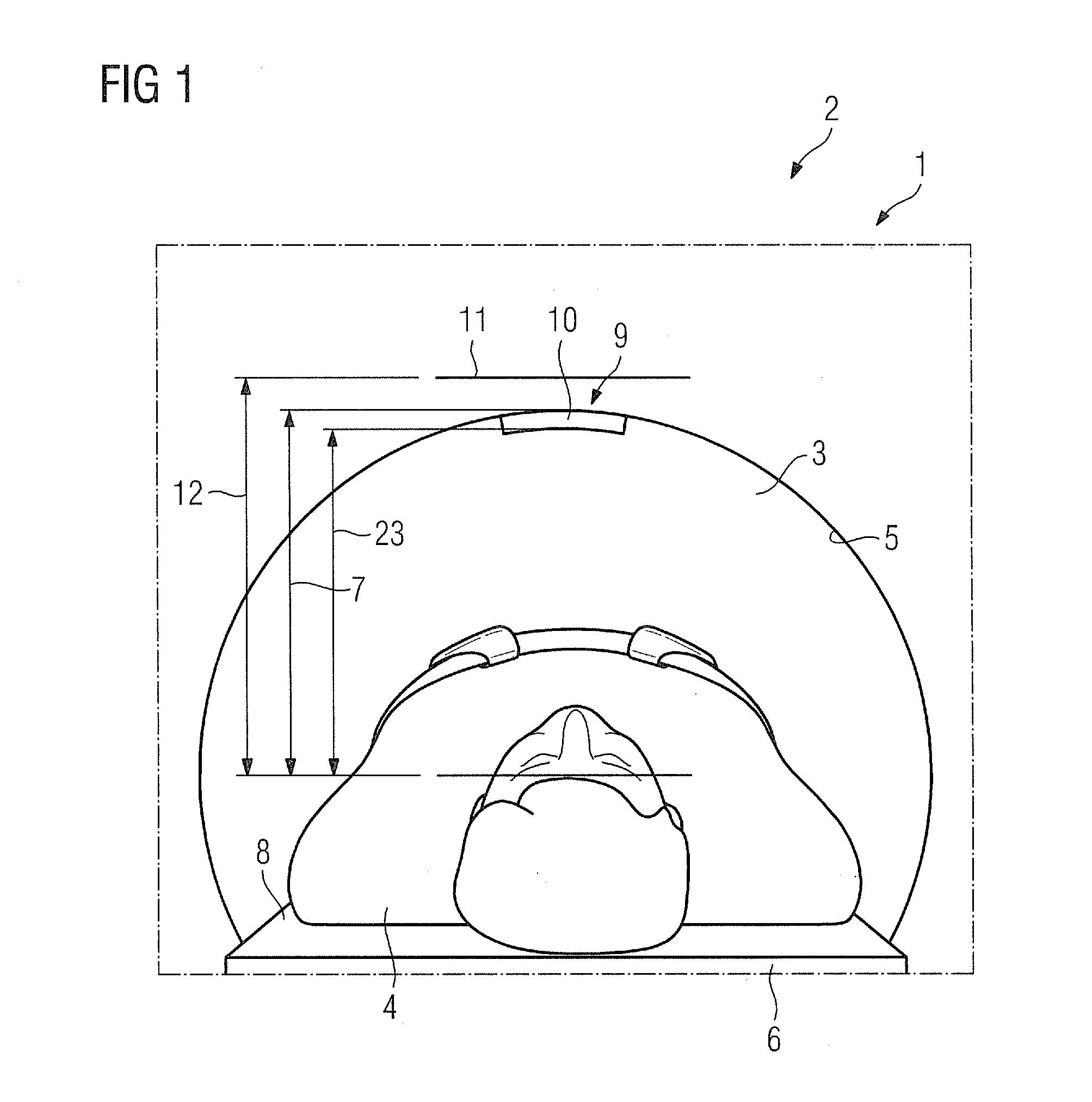
[0016]FIG. 1 shows a schematic diagram of an inventive medical imaging device 1, in the present exemplary embodiment formed by a magnetic resonance device 2. The magnetic resonance device 2 comprises a receiving region 3 to receive a patient 4. The receiving region 3 is tubular, in particular circular cylinder-shaped, and enclosed by a wall 5 of the magnetic resonance device 2. The wall 5 of the magnetic resonance device 2 here is formed by a housing shell of the magnetic resonance device 2. In an alternative embodiment of the invention the medical imaging device 1 can also be formed by a computed tomography device and / or further medical imaging device, which appear useful to the person skilled in the art, having an in particular tubular receiving region 3 to receive the patient 4. A tubular receiving region 3 can also have a D-shaped cross section. The receiving region 3 can also be configured as C-shaped.

[0017]For an imaging magnetic resonance examination the patient 4 is position...


PUM


Abstract

A medical imaging device having a tubular receiving region to receive a patient on a patient couch is proposed. The medical imaging device has a wall at least partially enclosing the receiving region. The medical imaging device features a film disposed on the wall at least partially enclosing the receiving region for generating at least one virtual image. The virtual image refers to a visual mapping of a light-reflecting object and / or an illuminated object.

Description

CROSS REFERENCE TO RELATED APPLICATIONS[0001]This application claims priority of German application No. 10 2010 039 469.6 filed Aug. 18, 2010, which is incorporated by reference herein in its entirety.FIELD OF THE INVENTION[0002]The present invention relates to a medical imaging device having an in particular tubular receiving region to receive a patient on a patient couch, and a wall at least partially enclosing the receiving region.BACKGROUND OF THE INVENTION[0003]Medical imaging devices, for example magnetic resonance devices or computed tomography devices, comprise a receiving region, in particular a circular cylinder-shaped and / or tubular receiving region to receive a patient. In conventional medical imaging devices this receiving region has a maximum diameter of approx. 60 cm to 70 cm. The patient lies on a patient couch inside this receiving region for a medical examination and / or for medical imaging. The distance between the face and / or eye region of the patient and a wall o...

Claims


Application Information

Patent Timeline
IPC IPC(8): A61B6/00
CPCA61B5/0555A61B6/032G01R33/288A61B2560/06G01R33/283A61B6/44A61B5/055
Inventor MACIEJEWSKI, BERND
Owner SIEMENS HEALTHCARE GMBH
Learn More