Tube connection assembly

a technology of connection assembly and tube, which is applied in the direction of connection contact member material, coupling device connection, hose connection, etc., can solve the problems of difficult to maintain the tolerances of parts, difficult to ensure a specific mating force, and manufacturing difficulties, and achieve the effect of simplifying the die structure and simple structur

Inactive Publication Date: 2008-07-01
TOYODA GOSEI CO LTD
View PDF18 Cites 65 Cited by
  • Summary
  • Abstract
  • Description
  • Claims
  • Application Information

AI Technical Summary

Benefits of technology

[0007]An advantage of some aspects of the invention is to provide a tube connection assembly that can, using a simple structure, hold the mating member on the male member, that can set easily a specific value for the mating-force between the male member and the female member, and that can simplify the die structure.
[0008]The present invention for connecting a male member to a female member comprises a male member that has a flow path that connects to a tube, a female member that has a flow path that connects to another tube, and a mating member that is interposed between the male member and the female member. The male member is provided with a tube-shaped male body that forms a flow path, and a retaining part that is formed on the outer peripheral part of the male body. The mating member is held by the retaining part, and is provided with a mating part, formed into a C-shape from an elastic member, with a portion thereof mating with the female member. The female member is provided with a tube-shaped female body forming a flow path, a receiving part, formed at an opening end part of the female body, into which the male member is fitted, and a mating hole, formed passing through the receiving part, into which the mating part of the mating member, supported on the male member, is inserted in the radial direction. The retaining part has a rotational locking part for preventing the rotation of the mating member, where the mating member is formed so as to mate with the female member through insertion into the mating hole by decreasing or increasing size in the radial direction in a state that is rotationally locked by the rotational locking part.
[0010]Consequently, given the two connection assembly, the mating member, at the time that the tube is installed, reduces and increases in size in the radial direction, supported in a stabilized state by the rotational locking part of a support part that is not circular in its cross-section, eliminating the need for troublesome operations for positioning the mating member, providing superior ease of operation.
[0011]Moreover, the mating part of the mating member is configured to mate with the female member through insertion into a mating hole that is formed through the receiving part of the female member, making it possible to simplify the structure by eliminating the need for high dimensional precision in, for example, the depth of the retaining groove in the female member in order to maintain the amount of material in the mating member that catches in the female member within a specific range, as described in the conventional technology.
[0012]Furthermore, the mating hole in the female member can be manufactured easily using an extrusion molding method using a slide die, or manufactured using a drilling / machining method, because the structure is one wherein a portion of the receiving part forms a through hole, and thus there is superior manufacturability.
[0013]As a preferred form of the present invention, the rotational locking part is provided with a base part wherein a portion of the outer peripheral part of the male member has a non-circular cross-sectional shape, where the mating member can be structured to form a foundation part at the base part. This structure makes it easy to structure the rotational locking part of the mating member.

Problems solved by technology

However, in the conventional tube connection assembly, a complex die structure is required to fabricate the mating groove on the inner peripheral part of the female member, causing difficulties in manufacturing.
Moreover, because steel wire, or the like, that can be subjected to elastic deformation is used in the mating member, it is difficult to maintain the tolerances of the part that catches, by protruding into the mating groove, within a specific range, and hence there has been a problem with difficulty in insuring a specific mating force.
Moreover, while the C-shaped mating member must prevent rotation of the positioning on the outer peripheral part of the male member, the structure to do so is complex, and there has also been a problem in difficulty in the positioning operations.

Method used


Image

  • Tube connection assembly
  • Tube connection assembly
  • Tube connection assembly

Examples


Embodiment Construction

[0025]Next, preferred examples of embodiment according to the present invention will be explained in order to further explain the structure and operation of the present invention.[0026](1) Schematic Structure of the Tube Connection Assembly

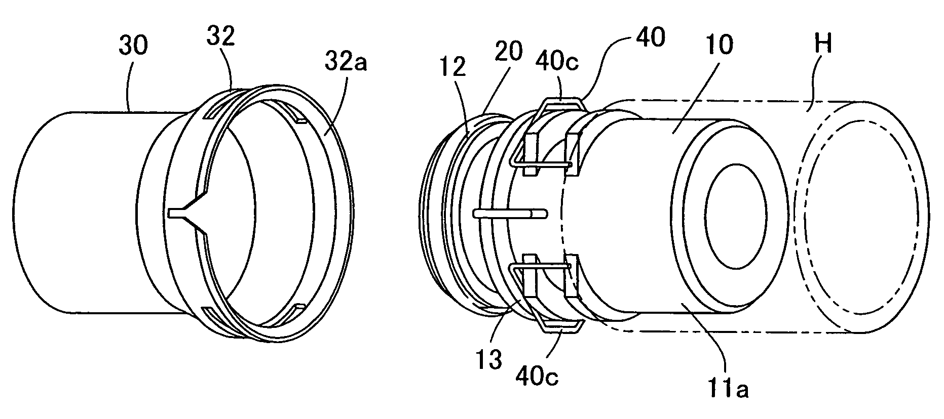
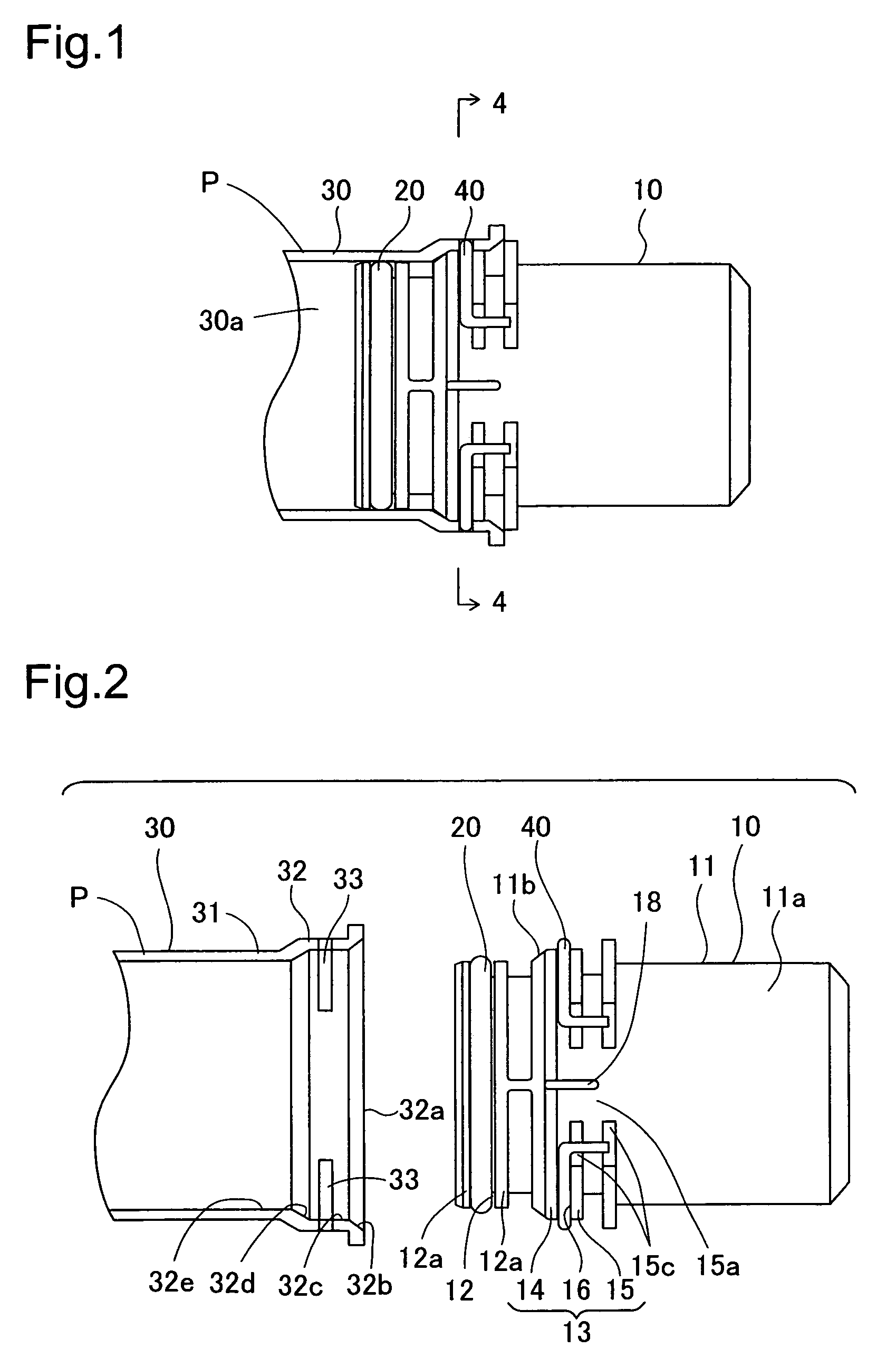
[0027]FIG. 1 is a partial cutaway side view of a tube connection assembly according to an embodiment according to the present invention. In FIG. 1, the tube connection assembly is used in, for example, radiator hoses in automobile engines, and is provided with a cylindrical male member 10, an O-ring 20, a female member 30 that is formed on the end part of a pipe P, and a mating member 40, where the O-ring 20 and a mating member 40 are equipped on the male member 10. The mating member 40, installed on the male member 10, mates with the female member 30 to connect the male member 10 to the female member 30.[0028](2) Structure of Each Part

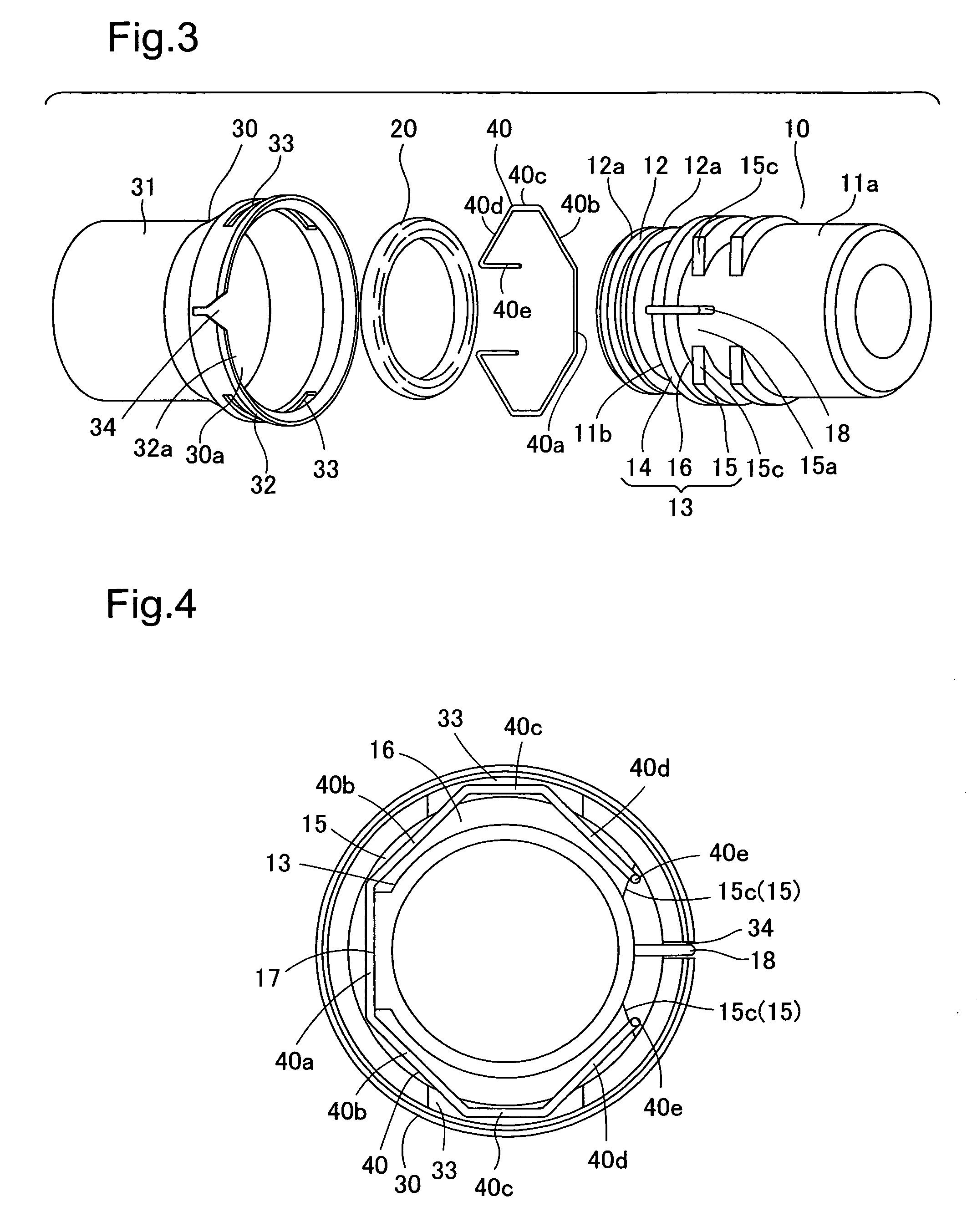
[0029]FIG. 2 is a side view showing the state of the tube connection assembly prior to making the connection, and...


PUM


Abstract

A tube connection assembly comprises a male member, a female member and a mating member. The male member is provided with a retaining part that is formed with a non-circular cross-section on the outer peripheral part of a male body. The mating member is held by the retaining part, is formed from an elastic material having a C-shape, and has, on a portion thereof, mating parts. The female member is provided with a receiving part in which the male member is inserted, and mating holes and formed through the receiving part. The mating member is held, so as to prevent rotation, by a base part of a retaining part that has a non-circular cross-section as a part of the outer peripheral part of the male body, and decreases or increases in diameter in the radial direction to mate with the female member through insertion into the mating holes.

Description

[0001]This application claims the benefit of and priority from Japanese Application No. 2005-215838 filed Jul. 26, 2005, the content of which is incorporated herein by reference.BACKGROUND OF THE INVENTION[0002]1. Field of the Invention[0003]The present invention relates to a tube connection assembly for connecting hoses or pipes that carry fluids.[0004]2. Description of the Related Art[0005]Conventional, a tube connection assembly has been known in JP-A-6-50482. The tube connection assembly has interposed a mating member between a male member and a female member that are connected to pipes or hoses, to connect together the male member and the female member. The mating member is formed by bending, for example, a C-shaped steel wire, or the like, and attaching to the outer peripheral part of a male member, which is circular in its cross-section. When the male member is inserted into the female member in order to connect the male member and the female member, the mating member, fasten...

Claims


Application Information

Patent Timeline
Patent Type & Authority Patents(United States)
IPC IPC(8): F16L39/00
CPCF16L33/227F16L37/088H01R13/6277H01R13/6275H01R13/5219F16L37/0885
Inventor TAGA, MASAYUKIYAMAGUCHI, HIROSHIISHIGURO, KEIJIOHI, SHIGEOMURASE, KAZUYOSHI
Owner TOYODA GOSEI CO LTD
Why Eureka
Try Eureka