Inline transfer system and method

a transfer system and transfer method technology, applied in the field of inline transfer system and method, can solve the problems of affecting the use of the transfer system, the failure of the cassette, the failure of the stocker, the inability to adjust the transfer system, etc., and achieves the effects of less damage and contamination, secure and clean transport, and less damage and contamination

Inactive Publication Date: 2008-07-01
SAMSUNG DISPLAY CO LTD
View PDF25 Cites 26 Cited by
  • Summary
  • Abstract
  • Description
  • Claims
  • Application Information

AI Technical Summary

Benefits of technology

[0009]The present invention provides an advantageous system and method for transferring and processing fragile objects, such as glass substrates used in the manufacture of LCDs, in which cleanliness and secure transport are of high concern. A rotary conveyor utilizes a plurality of air nozzles to transport substrates without making direct contact between the air nozzle structure and the substrate, thereby allowing for clean and secure transport of the substrate. Coupled to the rotary conveyor are at least two independent processing units or at least two independent inspection devices.
[0010]According to one embodiment of the present invention, an inline transfer system is provided, including a rotary conveyor including a panel, and a plurality of air nozzles operably coupled to the panel, wherein the plurality of air nozzles inject air to move a substrate above the plurality of air nozzles without the plurality of air nozzles making contact with the substrate. At least two processing units are operably coupled to the rotary conveyor, wherein the at least two processing units operate independently of each other providing operating flexibility and efficiency.
[0013]Advantageously, the present invention allows for the secure and clean transport and processing of glass substrates and other fragile objects, resulting in higher yields with less damage and contamination. The present invention is also advantageous for providing flexibility and efficiency such that processing may occur in parallel and not be delayed when one line has a malfunction.

Problems solved by technology

However, as glass substrates are increasing in size, a transfer system using the cassette, stocker, and indexer becomes more difficult to use because a typical cassette, stocker, or indexer transfers a plurality of glass substrates, and thus an existing cassette, stocker, or indexer must be made larger to transfer substrates of a larger size.
Furthermore, several disadvantages occur in a typical transfer system with larger glass substrates, such as inefficiency, lower yield due to breaks and contamination, and lack of flexibility.

Method used


Image

  • Inline transfer system and method
  • Inline transfer system and method
  • Inline transfer system and method

Examples


first embodiment

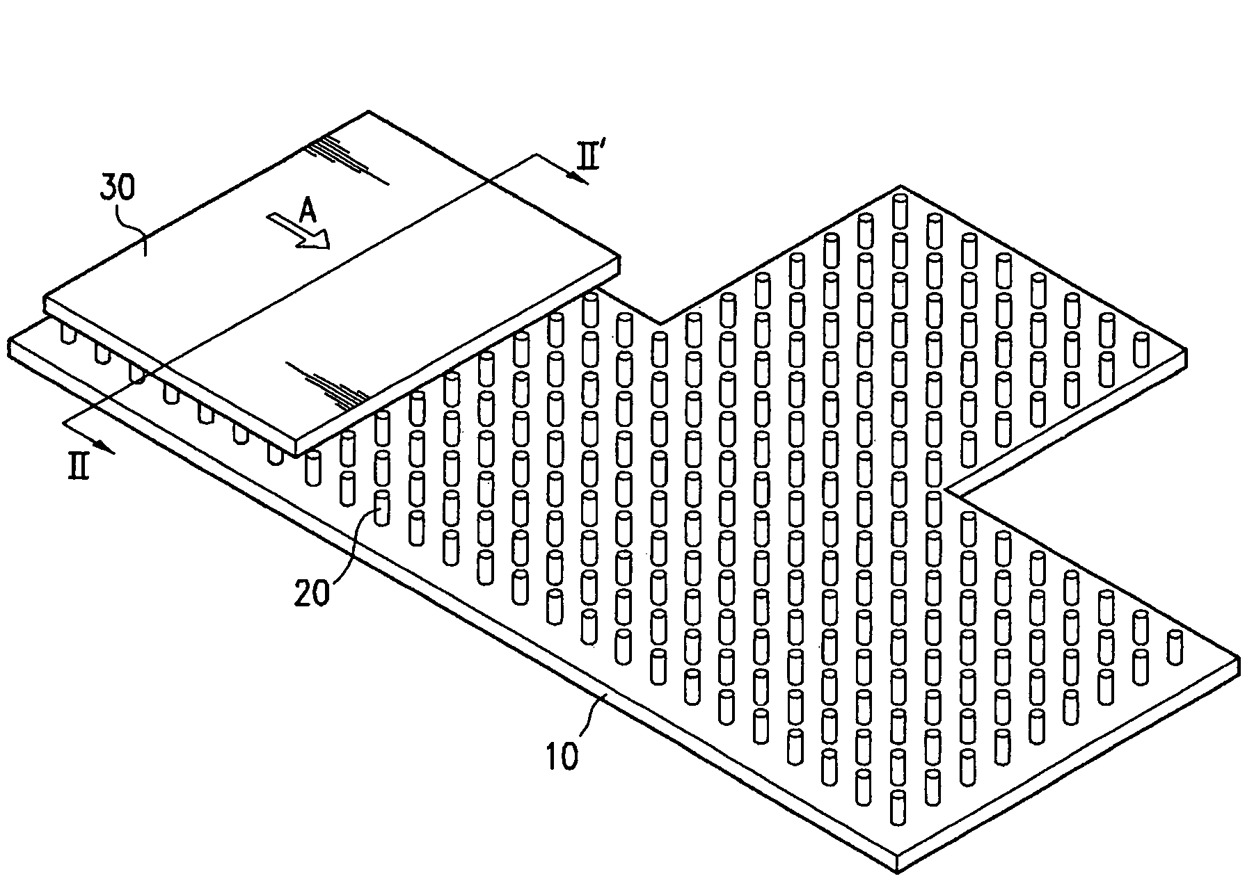
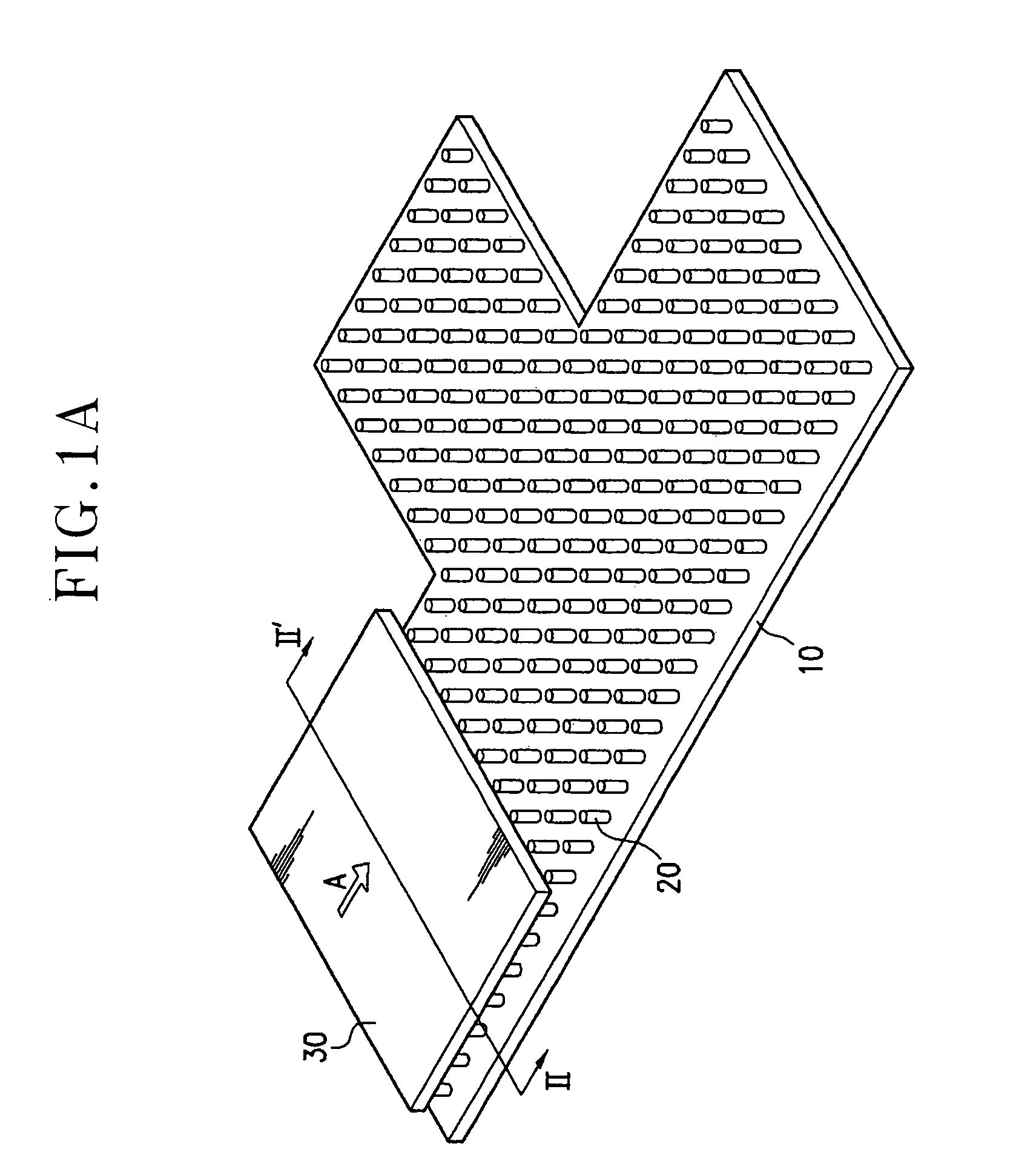
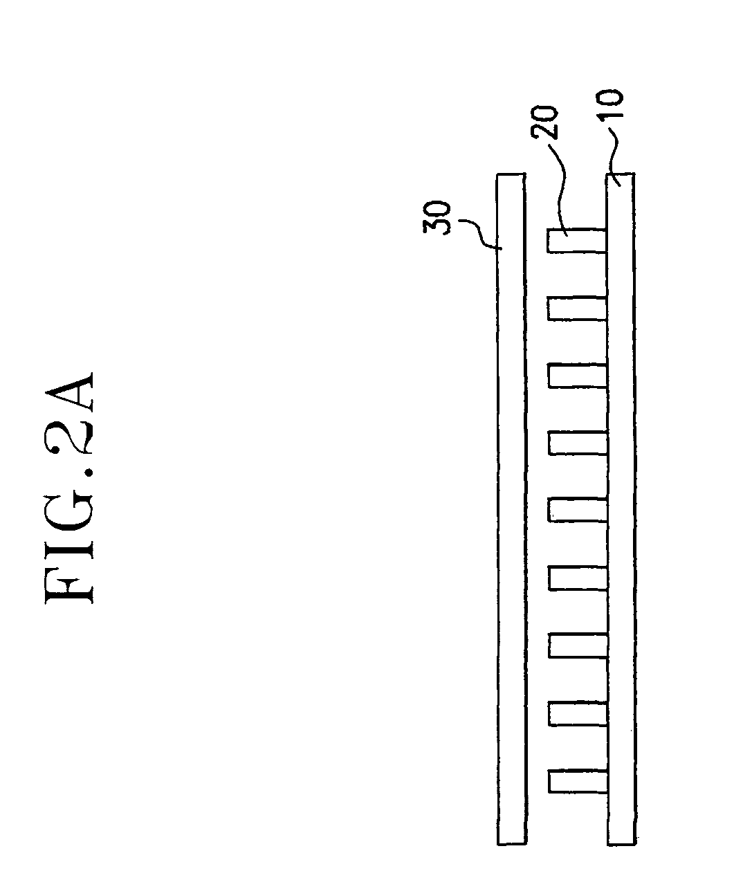
[0096]FIGS. 1A-8A and 13A illustrate a transfer apparatus according to the present invention. FIG. 1A is a perspective view of an example of the transfer apparatus showing a state in which a glass substrate is stopped. FIG. 2A is a sectional view of the transfer apparatus shown in FIG. 1A taken along the line II-II′. FIG. 3A is a perspective view of an example of the transfer apparatus showing a state in which the glass substrate is being transferred. FIG. 4A is a sectional view of the transfer apparatus shown in FIG. 3A taken along the line IV-IV′. FIG. 5A is a perspective view of an example of the transfer apparatus showing a state in which the glass substrate is stopped at a branch point. FIGS. 6AA and 6BA are sectional views of the transfer apparatus shown in FIG. 5A taken along the lines VIa-VIa′ and VIb-VIb′, respectively. FIG. 7A is a perspective view of an example of the transfer apparatus showing a state in which the glass substrate is transferred from a branch point to a b...

second embodiment

[0112]FIG. 9A is a perspective view of a transfer apparatus according to the present invention, and FIG. 10A is a lateral view of the transfer apparatus shown in FIG. 9A. The same reference numerals in the drawings mentioned above indicate similar parts for performing similar functions.

[0113]As shown in FIGS. 9A, 10A, and 13A, a transfer apparatus according to the second embodiment of the present invention includes a support panel 10 operably coupled to a transfer means 50 for transferring a transfer object 30. Transfer means 50 includes a connection body 51 and a guide line 52 on which connection body 51 is operably coupled and moved by sliding.

[0114]A plurality of air nozzles 20 are arranged on support panel 10, and in a similar manner as described above with respect to the first embodiment, the plurality of air nozzles 20 fix the position of transfer object 30 by injecting or sucking air to form a vacuum status inside each of the plurality of air nozzles 20 while maintaining a sp...

third embodiment

[0121]It is also possible to pick up and transfer the transfer object 30 from above as is described in a third embodiment below.

[0122]FIG. 11A is a perspective view of a transfer apparatus according to the third embodiment of the present invention, and FIG. 12A is a lateral view of the transfer apparatus shown in FIG. 11A. The same reference numerals as in drawings mentioned above indicate similar parts for performing similar functions.

[0123]As shown in FIGS. 11A, 12A, and 13A, a transfer apparatus according to the third embodiment of the present invention includes a support panel 10 and a transfer means 50 for transferring the support panel 10. Transfer means 50 includes a connection body 51 connected to a top portion of support panel 10 and a guide line 52 on which connection body 51 is operably coupled and moved by sliding.

[0124]A plurality of air nozzles 20 are arranged under support panel 10, and the plurality of air nozzles 20 fix the position of transfer object 30 by injectin...


PUM

PropertyMeasurementUnit
angleaaaaaaaaaa
angleaaaaaaaaaa
angleaaaaaaaaaa

Abstract

An inline transfer system and method are provided for the secure transport and efficient processing of substrates such as glass substrates or semiconductor devices. A rotary conveyor is provided that includes a plurality of air nozzles which inject air to move a substrate above the plurality of air nozzles without the plurality of air nozzles making contact with the substrate. At least two independent processing units are operably coupled to the rotary conveyor. Advantageously, because a plurality of substrates may be processed in parallel, greater efficiency and flexibility are provided. Because the substrate can be moved without physical contact between the structure of the air nozzles and the substrate, the transfer is secure, clean, and efficient.

Description

BACKGROUND[0001](a) Field of the Invention[0002]The present invention relates to an inline transfer system and method, and more particularly to an inline transfer system and method for processing glass substrates.[0003](b) Description of Related Art[0004]In general, a transfer system operates to move a transfer body by placing the transfer body onto a conveyor and sliding the conveyor using an operating roller connected to an operating motor. The conventional conveyor system uses a motor for power to move a body and a chain, a gear, or a belt for the purpose of power transfer.[0005]The transfer system can be utilized to transfer glass substrates in manufacturing liquid crystal displays (“LCDs”) in one example. An LCD is one of the most popular flat panel displays, which includes two panels provided with two kinds of electrodes generating an electric field and a liquid crystal layer interposed therebetween. The LCD displays images by controlling light transmittance, and the control o...

Claims


Application Information

Patent Timeline
Patent Type & Authority Patents(United States)
IPC IPC(8): B65G51/00G02F1/13B65G49/05B65G49/06H01L21/677H01L21/68
CPCB65G49/065H01L21/67784B65G2207/06B65G2249/04B65G2249/02G02F1/13
Inventor CHANG, WON-KIEYOON, GI-CHEONAN, GEUN-SOO
Owner SAMSUNG DISPLAY CO LTD
Why Eureka
Try Eureka