Apparatus including pin adapter for air bearing surface (ABS) lapping

Active Publication Date: 2008-07-01
IBM CORP
View PDF13 Cites 20 Cited by
  • Summary
  • Abstract
  • Description
  • Claims
  • Application Information

AI Technical Summary

Benefits of technology

[0013]In one embodiment, the adapter may be constructed from a polyimide material. Still yet, the adapter may include a pair of holes formed therein for coupling with a pair of holes formed in the lapping cable via a pair of alignment pins. As a further option, t

Problems solved by technology

While the lapping cable 200 of FIG. 2A works well with the prior art wafers 100 of FIG. 1, difficulty arises when used with wafers having

Method used


Image

  • Apparatus including pin adapter for air bearing surface (ABS) lapping
  • Apparatus including pin adapter for air bearing surface (ABS) lapping
  • Apparatus including pin adapter for air bearing surface (ABS) lapping

Examples


Embodiment Construction

[0028]The following description is the best embodiment presently contemplated for carrying out the present invention. This description is made for the purpose of illustrating the general principles of the present invention and is not meant to limit the inventive concepts claimed herein.

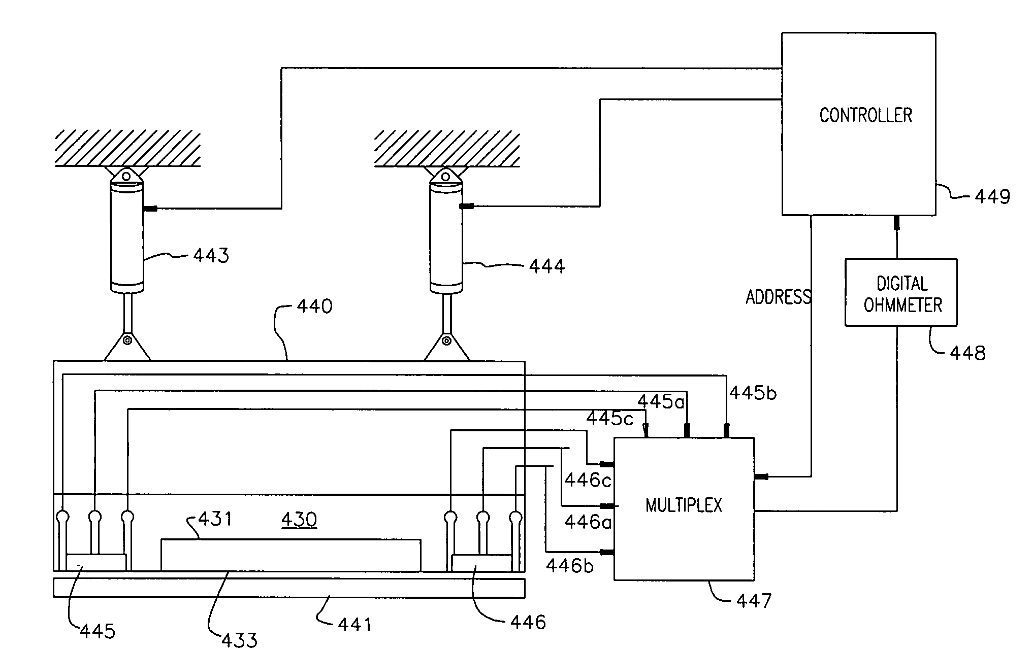
[0029]FIG. 4 illustrates a typical lapping system for lapping a flat surface 433 of a head of a wafer. A lapping fixture 440 holds the flat surface 433 in position over a lapping plate 441. The lapping plate 441 is a flat abrasive surface for accurately lapping the surface 433 to a final dimension.

[0030]The force applied to the lapping fixture 440 is derived from first and second pressure actuators 443 and 444. Varying the force applied by the actuators 443 and 444 against the flat surface 433 controls leveling of the lapped surface 433.

[0031]The lapping device insures that the throat heights and stripe heights for all of the heads are at the correct length.

[0032]After completion of lapping the surfac...


PUM

PropertyMeasurementUnit
Diameteraaaaaaaaaa

Abstract

A system is provided for measuring a head during a lapping process. First provided is a wafer including at least one head each having an electrical lapping guide (ELG), a plurality of wafer contacts in electrical communication with the ELG, and a closure formed thereon defining a slot in which the wafer contacts are positioned. Also included is a lapping cable coupled to a testing device. The lapping cable includes a plurality of lapping cable contacts. An adapter includes a plurality of adapter contacts in electrical communication with the lapping cable contacts. The adapter contacts are removably positionable in electrical communication with the wafer contacts for measuring the head during a lapping process.

Description

FIELD OF THE INVENTION[0001]The present invention relates to thin film recording heads, and more particularly, this invention relates to testing electrical lapping guides (ELGs) on thin film recording heads during a lapping process.BACKGROUND OF THE INVENTION[0002]Conventional recording heads for linear tape drives have small transducers incorporated into a large head assembly to span the full width of the tape. For recording heads fabricated using thin film wafer technology, this requires that the head either be fabricated individually on a wafer which is at least as wide as the recording tape and lapped individually to the proper shape, or be fabricated as a small part and assembled with larger pieces. In the second case, either the small parts or the full assembly is lapped to the proper shape.[0003]Prior art FIG. 1 illustrates a wafer 100 on which a plurality of heads 102 may be manufactured. It should be noted that the wafer 100 is set forth for illustrative purposes only and t...

Claims


Application Information

Patent Timeline
IPC IPC(8): B24B49/10B24B37/04B24B49/02G11B5/187G11B5/31
CPCB24B37/042B24B49/02G11B5/1871G11B5/3173G11B5/3103Y10T29/53165Y10T29/49048Y10T29/5313Y10T29/49046G11B5/3163
Inventor BISKEBORN, ROBERT G.
Owner IBM CORP
Why Eureka
Try Eureka