Power transmission device

a technology of torque limiter and transmission device, which is applied in the direction of couplings, slip couplings, gearing, etc., can solve problems affecting achieve the effects of enhancing the accuracy of torque limiters, and preventing a change in coefficients of friction

Active Publication Date: 2008-07-01
DENSO CORP
View PDF7 Cites 4 Cited by
  • Summary
  • Abstract
  • Description
  • Claims
  • Application Information

AI Technical Summary

Benefits of technology

[0007]The present invention has been accomplished to solve the above problems. It is an object of the present invention to provide a power transmission device characterized in that: it is possible to prevent a change in the coefficient of friction caused by the invasion of water and foreign objects from the outside into the screw fastening portion; it is also possible to prevent a change in the coefficient of friction caused by the leakage of oil, which was coated on the screw portion at the time of the initial assembling, when time has passed; the accuracy of the torque limiter is enhanced and the operation of the torque limiter is stabilized; the manufacturing cost is reduced; and the manufacturing and assembling work is simplified.
[0008]A power transmission device of the present invention includes a pulley, a hub, a torque transmitting elastic member and a torque limiter. The hub and the rotary shaft are connected to each other by the screwing engagement of a female screw portion, which is formed on the inner circumferential face of the hub, with a male screw portion which is formed on the outer circumferential face of the forward end portion of the rotary shaft. A sealing means for tightly sealing between the hub and the rotary shaft is provided in a portion adjacent to the front of this screw engaging portion or in portions adjacent to the front and the rear portion of this screwing portion. Due to this structure, it is possible to prevent water from getting into the screw engaging portion from the outside and, further, it is possible to prevent oil, which was coated on each screw portion at the time of initial assembling, from leaking outside. Accordingly, it is possible to prevent a change in the coefficient of friction caused by the corrosion in each screw portion. Therefore, the operation of the torque limiter can be stabilized.
[0009]In a power transmission device of the present invention, the torque limiter is arranged on the rotary shaft side. Therefore, the torque limiter can be a simple structure in which a small diameter portion is provided on the rotary shaft.

Problems solved by technology

Further, in the case where the screwing engagement portion is covered with oil so as to stabilize the coefficient of friction, oil flows out while the device is actually being used, and the coefficient of friction changes, which affects the accuracy of the torque limiter.

Method used


Image

  • Power transmission device
  • Power transmission device
  • Power transmission device

Examples


fourth embodiment

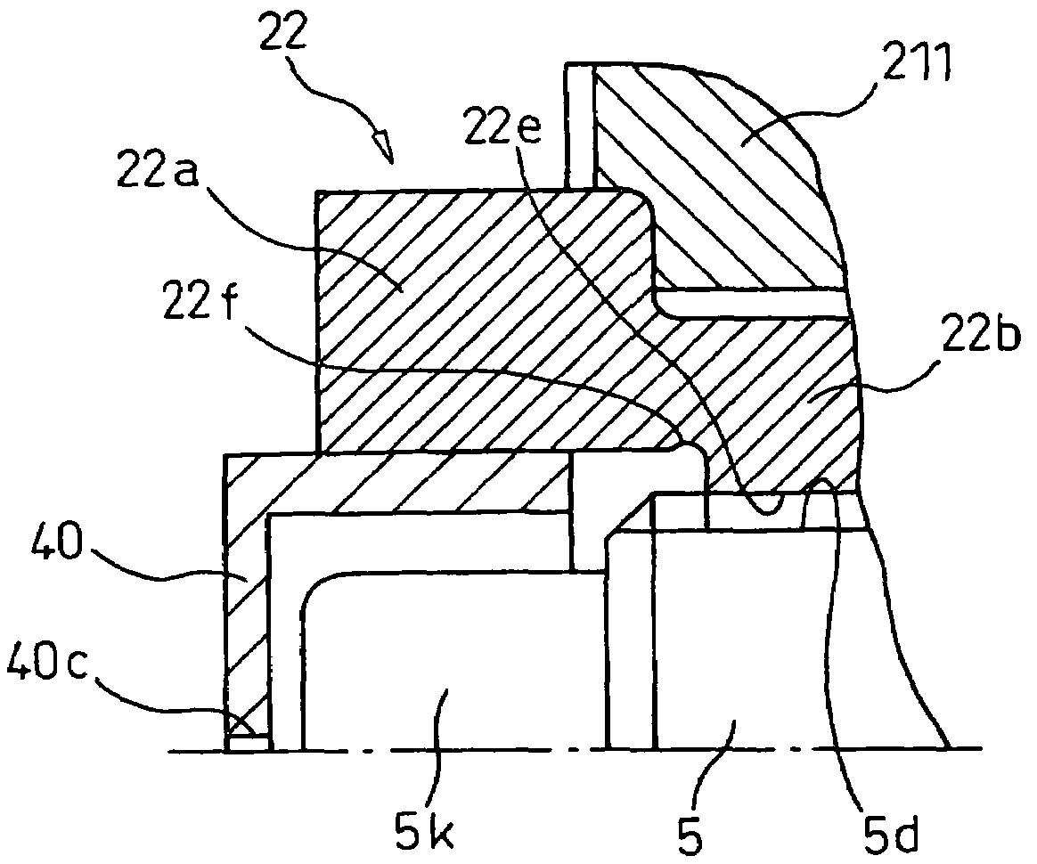
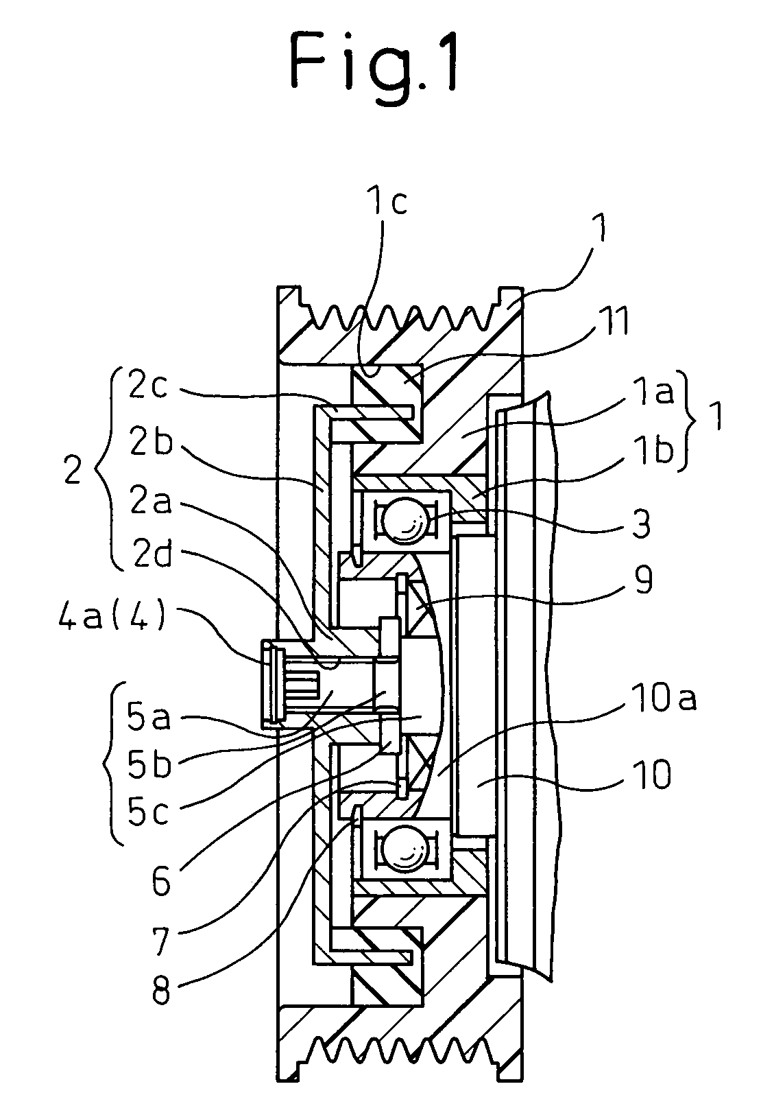
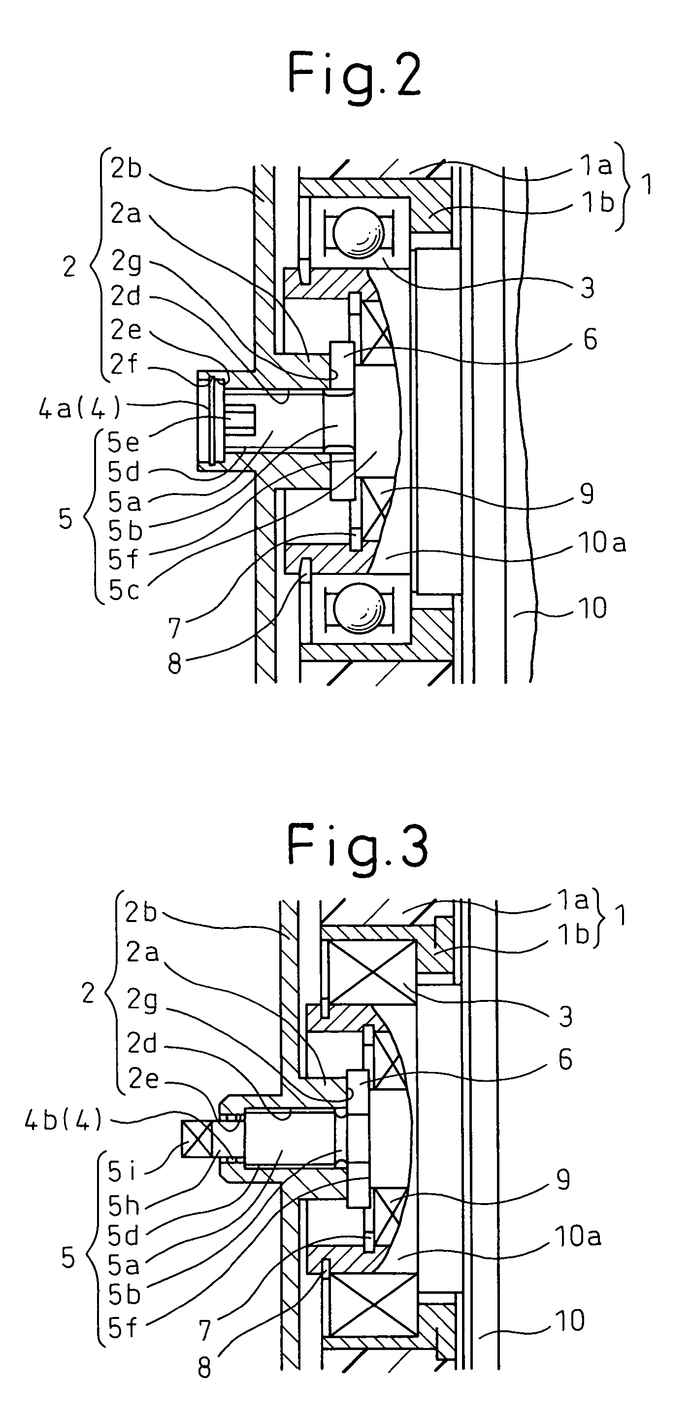
[0085]Concerning the rotary shaft 5 of the compressor, in the forward end portion 5a in which the male screw portion 5d is formed, the plane portion 5i, used for assembling, is provided. A portion of the outer circumferential face on the front side of the forward end portion 5a is a seal portion 5j in which the male screw portion 5d is not formed. In the fourth embodiment, the torque limiter portion 5b on the rotary shaft 5 side is abolished. This portion becomes the shaft portion 5m, the outer diameter of which is the same as that of the forward end portion 5a.

[0086]The hub portion 21, the limiter portion 22 and the rotary shaft 5, which are composed as described above, are combined with each other as follows. The female screw portion 21f of the large inner diameter portion 21c and the male screw portion 22d of the large outer diameter portion 22a are screwed and engaged with each other. The limiter portion 22 is inserted into the hub portion 21 so that the seating face 22c of the...

fifth embodiment

[0095]Between the tool shape portion 5k of the rotary shaft 5 and the inner circumferential face of the large outer diameter portion 22a of the limiter portion 22, the packing member 4e, which is a characteristic seal means of the fifth embodiment, is provided.

[0096]FIGS. 9 to 14D are views respectively showing a shape of the packing member 4e of each embodiment. FIG. 9 is a plan view of the packing member 4e of Example 1. In Example 1, the inner circumference of the packing member 4e is formed into a hexagon, and the cutout 4f is provided in each corner portion of this hexagon. The cutout portion 4f functions as a hole from which the inner pressure is released. In this case, the outer circumference of the square shape portion 5k of the rotary shaft 5 is formed into a hexagonal shape according to the shape of the inner circumference of the packing member 4e.

[0097]FIG. 10A is a plan view and a sectional view of the packing member 4e of Example 2. In Example 2, the inner circumferenc...

sixth embodiment

[0122]FIGS. 17A-1 to 21-2 show various different examples of the cap, or the sealing means 4, of the

[0123]FIGS. 17A-1 and 17A-2 show a cap 41 of Example A. One end of the cap 41 of Example A is open and the other end is closed, that is, the cap 41 of Example A is formed into a cylindrical shape having a bottom portion. The cap 41 has a circumferential portion 41a.

[0124]FIGS. 17A-3 shows a cap like that of FIGS. 17A-2 that is made of elastic material.

[0125]FIGS. 17B-1 and 17B-2 show a cap 42 of Example B. In the cap 42 of Example B, one hole 42c, from which the inner pressure is released, is formed at the substantial center of the lid portion 42b of the cylindrical cap 42 having a bottom portion. A plurality of holes 42c, from which the inner pressure is released, may be formed. It is preferable that the area of one pressure releasing hole 42c is not less than 0.02 mm2. Accordingly, even when the temperature of the rotary shaft 5 is raised at the time of operating the compressor and...


PUM


Abstract

In the power transmission device having a torque limiting function for shutting off the transmission of an excessively high torque between the pulley 1 and the rotary shaft 5, the hub 2 and the rotary shaft 5 are connected to each other by means of screw engagement between the female screw portion 2d, which is formed on the inner circumferential face of the hub 2, and the male screw portion 5d which is formed on the outer circumferential face of the forward end portion 5a of the rotary shaft 5, and the seal means 4 for sealing between the hub and the rotary shaft is provided adjacent to the front face or the front and rear faces of the screw engaging portion. The torque limiting function may be provided on the rotary shaft side or the hub side.

Description

BACKGROUND OF THE INVENTION[0001]The present invention relates to a power transmission device having a torque limiting function. More particularly, the present invention relates to a power transmission device incorporated into a compressor of an air conditioner for vehicle use.[0002]In a conventional power transmission device for transmitting power to a compressor, in order to avoid the occurrence of a problem in which a belt of the compressor, which is used for transmitting power, is damaged when the compressor has seized due to a heavy load, a torque limiter is arranged in the power transmission device. For example, in the case of a torque limiter shown in the official gazette of JP-A-2003-206950, a portion of the power transmitting passage is composed of a screw-in connection.[0003]In the official gazette of JP-A-2003-206950, as shown in FIG. 22, the adapter B, from which the cylindrical limiter attaching portion B1 integrally protrudes, is press-fitted and fixed to the rotary sh...

Claims


Application Information

Patent Timeline
Patent Type & Authority Patents(United States)
IPC IPC(8): F16D9/04
CPCF16D9/08F16H55/36F16H35/10Y10S474/903
Inventor NOSAKA, MICHIYASUTABUCHI, YASUOUEDA, MOTOHIKOTADA, YOSHIKI
Owner DENSO CORP
Why Eureka
Try Eureka