Thermally contained/insulated phase change memory device and method (combined)

a phase change memory and phase change technology, applied in the field of high density memory devices, can solve the problems of controlling the operating current, the heat generated by that number of cells has the potential at least to degrade a memory unit, destroy it altogether, etc., and achieve the effect of improving the thermal isolation of the phase change material and improving the heat transfer characteristics

Active Publication Date: 2008-07-01
MACRONIX INT CO LTD
View PDF161 Cites 159 Cited by
  • Summary
  • Abstract
  • Description
  • Claims
  • Application Information

AI Technical Summary

Benefits of technology

[0011]An aspect of the invention is a memory device with improved heat transfer characteristics. The device first includes a dielectric material layer; first and second electrodes, vertically separated and having mutually opposed contact surfaces. A phase change memory element is encased within the dielectric material layer, including a phase-change layer positioned between and in electrical contact with the electrodes, wherein the lateral extent of the phase change layer is less than the lateral extent of the electrodes. An isolation material is positioned between the phase change layer and the dielectric layer, wherein the thermal conductivity of the isolation material is lower than the thermal conductivity of the dielectric material. The isolation layer isolates the material of the phase change layer from etching processes which may damage or undercut the material. In embodiments described herein, the isolation material also improves thermal isolation of the phase change material.

Problems solved by technology

A particular problem encountered in the prior art has been controlling the operating current, and the heat generated by that current.
The phase change process proceeds by joule heating of the phase change material, which produces two problems.
Second, the heat generated by that number of cells has the potential at least to degrade a memory unit, if not destroy it altogether.

Method used


Image

  • Thermally contained/insulated phase change memory device and method (combined)
  • Thermally contained/insulated phase change memory device and method (combined)
  • Thermally contained/insulated phase change memory device and method (combined)

Examples


Embodiment Construction

[0037]The following detailed description is made with reference to the figures. Preferred embodiments are described to illustrate the present invention, not to limit its scope, which is defined by the claims. Those of ordinary skill in the art will recognize a variety of equivalent variations on the description that follows.

[0038]With regard to directional descriptions herein, the orientation of the drawings establish their respective frames of reference, with “up,”“down,”“left” and “right” referring to directions shown on the respective drawings. Similarly, “thickness” refers to a vertical dimension and “width” to the horizontal. These directions have no application to orientation of the circuits in operation or otherwise, as will be understood by those in the art.

[0039]There follows a description of the phase change element and memory cell of the present invention, after which the process for fabricating them are discussed.

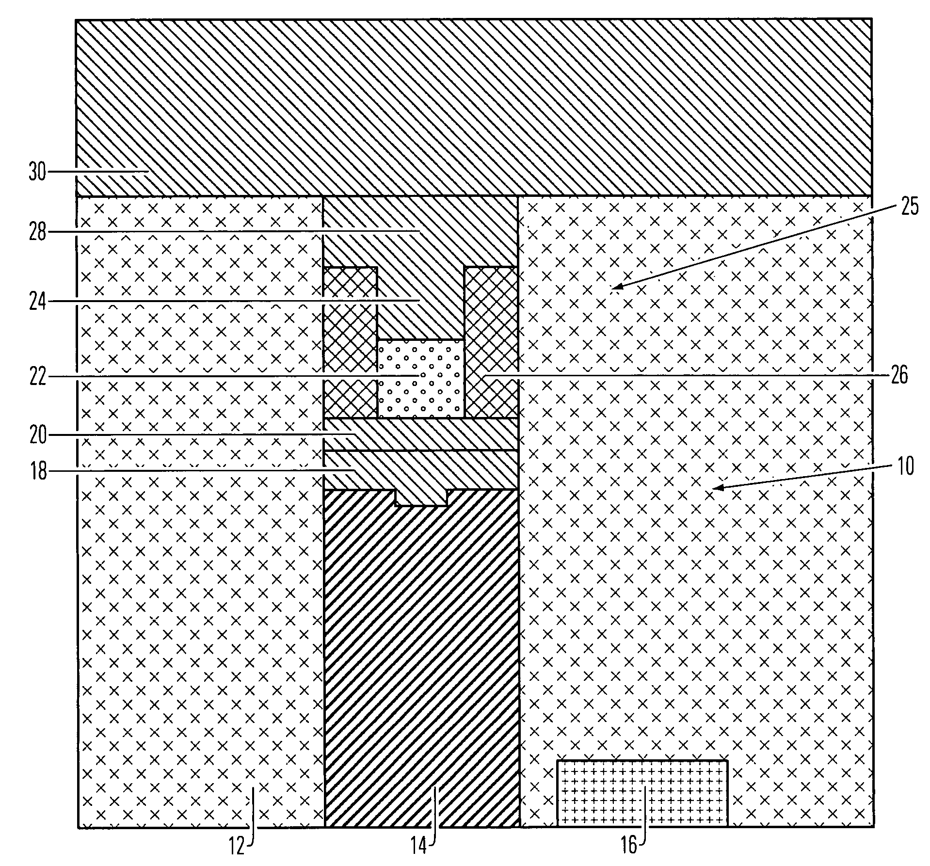
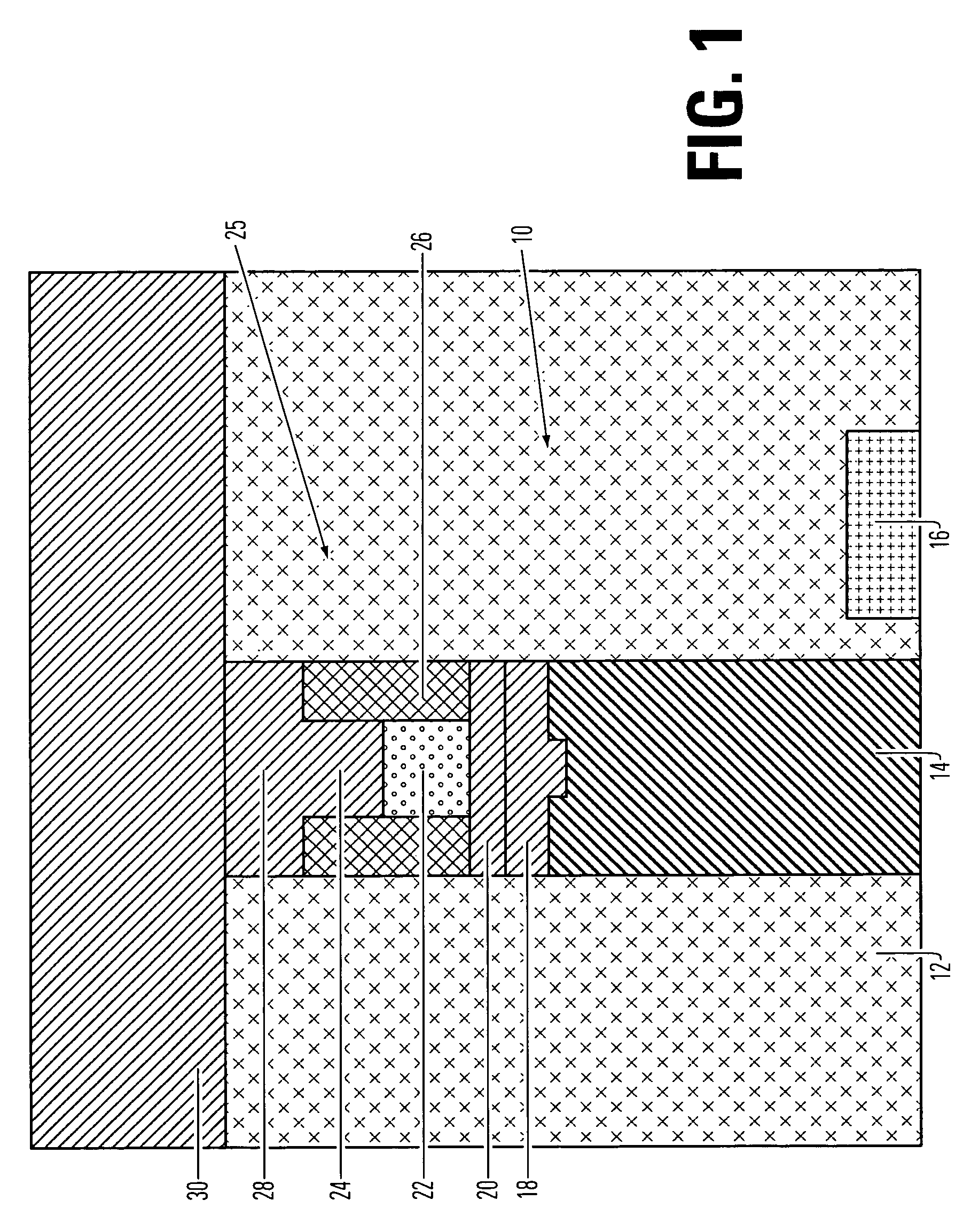
[0040]FIG. 1 depicts phase change memory element 10, an em...


PUM


Abstract

A memory device with improved heat transfer characteristics. The device first includes a dielectric material layer; first and second electrodes, vertically separated and having mutually opposed contact surfaces. A phase change memory element is encased within the dielectric material layer, including a phase-change layer positioned between and in electrical contact with the electrodes, wherein the lateral extent of the phase change layer is less than the lateral extent of the electrodes. An isolation material is positioned between the phase change layer and the dielectric layer, wherein the thermal conductivity of the isolation material is lower than the thermal conductivity of the dielectric material.

Description

REFERENCE TO RELATED APPLICATION[0001]This application claims the benefit of U.S. Provisional Patent Application No. 60 / 736,721 entitled THERMALLY CONTAINED / INSULATED PHASE CHANGE MEMORY DEVICE AND METHOD (COMBINED), filed on 15 Nov. 2005 by inventor Hsiang-Lan Lung. That application is incorporated by reference for all purposes.PARTIES TO A JOINT RESEARCH AGREEMENT[0002]International Business Machines Corporation, a New York corporation; Macronix International Corporation, Ltd., a Taiwan corporation; and Infineon Technologies A.G., a German corporation, are parties to a Joint Research Agreement.BACKGROUND OF THE INVENTION[0003]1. Field of the Invention[0004]The present invention relates to high density memory devices based on phase change based memory materials, including chalcogenide based materials and other materials, and to methods for manufacturing such devices, and most particularly to a phase change memory element having lowered current and improved heat control characterist...

Claims


Application Information

Patent Timeline
Patent Type & Authority Patents(United States)
IPC IPC(8): H01L29/02
CPCH01L45/06H01L45/1233H01L45/126H01L45/143H01L27/2436H01L45/1293H01L45/148H01L45/1675H01L45/144Y10S438/90H10B63/30H10N70/231H10N70/826H10N70/8413H10N70/8616H10N70/8825H10N70/884H10N70/8828H10N70/063
Inventor LUNG, HSIANG-LAN
Owner MACRONIX INT CO LTD
Why Eureka
Try Eureka