Backlight Module and Liquid Crystal Display using the same

a backlight module and liquid crystal display technology, applied in the field of backlight module and liquid crystal display, can solve the problems of high thermal resistance, inability to rapidly transfer heat to the metal frame, and inability to improve thermal transferring ratio, etc., to achieve rapid transfer, large size, and fast transfer

Inactive Publication Date: 2008-07-17
INNOLUX CORP
View PDF6 Cites 20 Cited by
  • Summary
  • Abstract
  • Description
  • Claims
  • Application Information

AI Technical Summary

Benefits of technology

[0015]In use, the composite film has a large size and covers a large part of the backlight module, and the light source unit is disposed adjacently to the exposed thermal transferring layer. Thus, the heat produced by the light source unit in use can be rapidly transferred to the thermal transferring layer, and can be quickly transferred to a comparatively low temperature region by the good thermal transferring characteristic, and the heat concentration phenomena is dismissed. In addition, the backlight module utilizes the large size of the thermal transferring layer to rapidly dismiss thermal to atmosphere. Therefore, the backlight module does not need a weighty metal frame, and can realize a high heat transferring results, which adds the usage life and the optical characteristics of the backlight module. Furthermore, the multiple piece can be a flexible piece. Thus, the backlight module and the liquid crystal display can be made to a flexible backlight module.

Problems solved by technology

Nevertheless, the PCB 120 and the metal frame 140 easily cause interspace therebetween, which makes the heat can not be rapidly transferred to the metal frame 140.
If the thickness is thicker, a thermal resistance is high and the thermal transferring ratio also can not be improved.
Inevitably, the thicker and larger frame 140 increases cost, weight, thickness, which lowers the competitive power.
Moreover, the use of thermal pad 130 also needs to add more cost and assembling time of the backlight module 100.

Method used


Image

  • Backlight Module and Liquid Crystal Display using the same
  • Backlight Module and Liquid Crystal Display using the same
  • Backlight Module and Liquid Crystal Display using the same

Examples


first embodiment

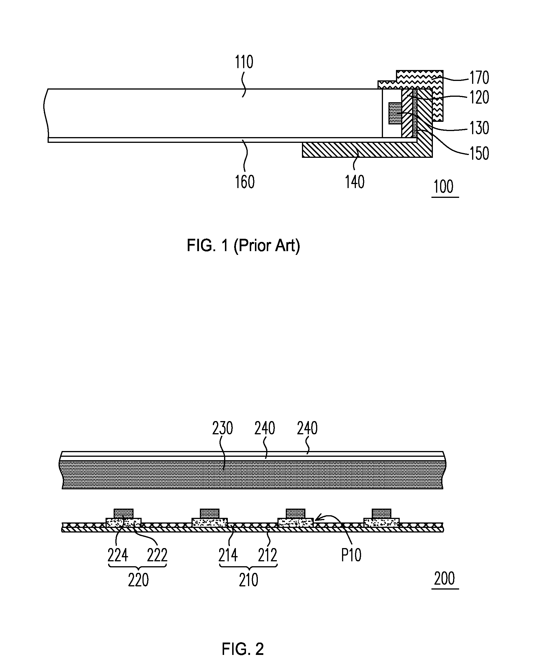
[0023]FIG. 2 is a partial cross-sectional view of a backlight module according to the present invention. The backlight module 200 has a composite film 210 and at least one light source unit 220. The composite film 210 has a thermal transferring layer 212 and a reflecting layer 214. The reflecting layer 214 is disposed on the thermal transferring layer 212. The reflecting layer 214 has at least one opening P10, which exposes a part of thermal transferring layer 212. The light source unit 220 is disposed adjacently to the opening P10, correspondingly. In this embodiment, number of the light source unit 220 and the opening P10 is multiple, and the plurality of light source units 220 and the openings P10 correspond to each other.

[0024]In the backlight module 200, the composite film 210 has a large size and covers a large part of the backlight module 200, and the light source unit 220 is disposed adjacently to the exposed thermal transferring layer 212. Thus, the heat produced by the lig...

second embodiment

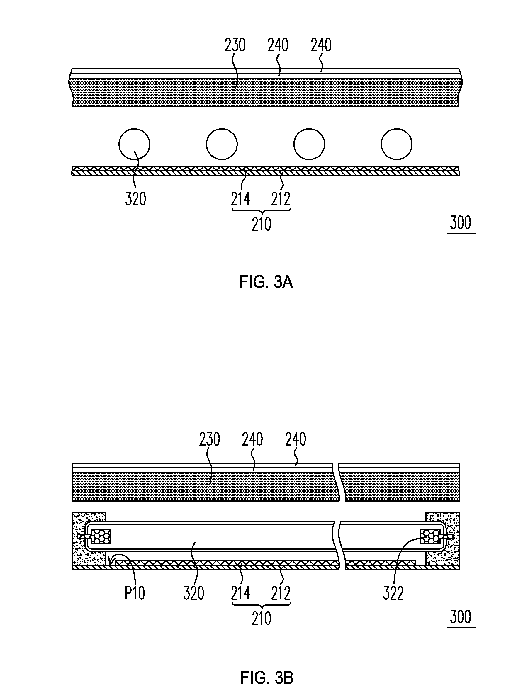
[0030]FIG. 3A and 3B show two partial cross-sectional views at two perpendicular directions of a backlight module according to the present invention. The backlight module 300 has a similar structure to the backlight module 200 except that a light source unit 320 is a cold cathode fluorescent lamp (CCFL), which does not directly contact with a thermal transferring layer 312. The backlight module 300 has a reflecting layer 214 having an opening P10. The opening P10 is under an electrode portion 322 of the light source unit 320, corresponding to an exposed portion of a thermal transferring layer 212. Thus, heat energy produced by the light source unit 320 can be rapidly transferred to a center portion of the thermal transferring layer 312 by the exposed portion thereof. Because the center portion of the thermal transferring layer 312 has a low temperature, which can effectively dissipate heat of the electrode portion 322 of the light source unit 320. Thus, the backlight module 300 also...

fifth embodiment

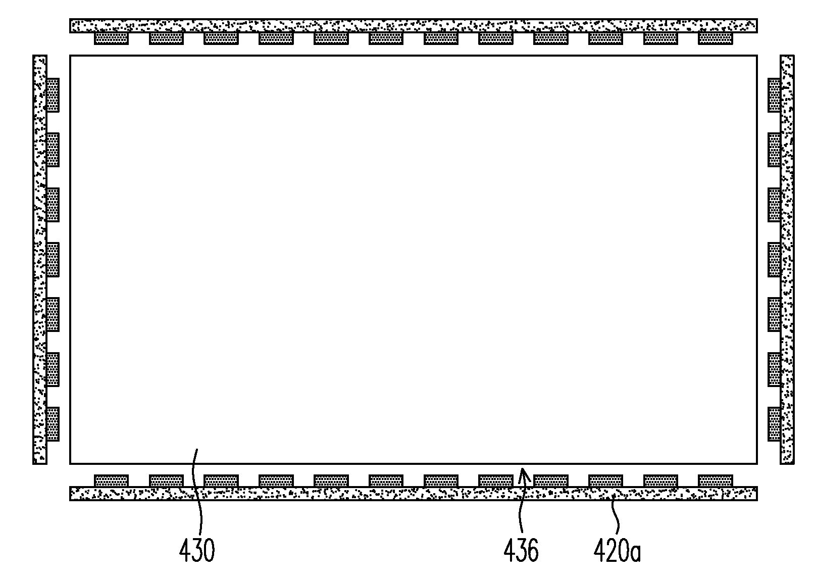
[0034]FIG. 4C shows a top view of a backlight module according to the present invention, which only show a light guide plate 430 and light source units. The backlight module 400a has a plurality of light incident surfaces 436, for example four incident surfaces. The plurality of light source units respectively faces the plurality of light incident surfaces 436. Each light source unit has a plurality of point light sources 420a, which emit light beams into the light guide plate 430 through the light incident surfaces 436.

[0035]FIG. 5 is a schematic view of a liquid crystal display according to the present invention. The liquid crystal display 500 has a liquid crystal panel 510 and a backlight module 520 disposed under the liquid crystal panel 510. The backlight module 520 has a same structure to that of the backlight module 400a.


PUM

PropertyMeasurementUnit
thicknessaaaaaaaaaa
thermalaaaaaaaaaa
thermal conductiveaaaaaaaaaa

Abstract

A backlight module includes a composite film, and at least one light source unit adjacent to at least one opening. The composite film has a thermal transferring layer and a reflecting layer, the reflecting layer being disposed at the thermal transferring layer and having the at least one opening exposing part of the thermal transferring layer. The backlight module can be used in a liquid crystal display. The liquid crystal display has the aforementioned backlight module and a liquid crystal panel, the backlight module being disposed under the liquid crystal panel.

Description

BACKGROUND[0001]The present invention relates to a light source unit module and a display, particular to a backlight module and a liquid crystal display using the same.[0002]A typical liquid crystal display is capable of displaying a clear and sharp image through millions of pixels that make up the complete image. The liquid crystal display has thus been applied to various electronic equipments, such as mobile phones and notebook computers, in which messages or pictures need to be showed. However, liquid crystals in the liquid crystal display do not themselves emit light. Rather, the liquid crystals have to be lit up by a light source unit so as to clearly and sharply display text and images. The light source unit may be ambient light, or a backlight module attached to the liquid crystal display.[0003]FIG. 1 shows a typical edge-type backlight module 100. The backlight module 100 has a light guide plate (LGP) 110, a printed circuit board (PCB) 120, a plurality of light emitting diod...

Claims


Application Information

Patent Timeline
Patent Type & Authority Applications(United States)
IPC IPC(8): G02F1/13357F21V29/00
CPCG02B6/0068G02B6/0073G02B6/0083G02F2001/133628G02F1/133603G02F1/133604G02B6/0085G02F1/133628
Inventor CHEN, YUNG-KAN
Owner INNOLUX CORP
Why Eureka
Try Eureka