Temperature controlled railway car

a temperature control and railway car technology, applied in the field of railway cars, can solve the problems of labor and time, significant raw materials, and difficulty in completing the manufacture and assembly of conventional boxcars

Inactive Publication Date: 2009-01-20
TRINITY IND INC
View PDF45 Cites 19 Cited by
  • Summary
  • Abstract
  • Description
  • Claims
  • Application Information

AI Technical Summary

Benefits of technology

[0012]A composite box structure formed in accordance with teachings of the present invention provides enhanced insulation, increased load carrying capacity, better temperature regulation, increased service life, and reduced maintenance costs as compared to a typical refrigerated boxcar. The present invention allows designing floor assemblies, sidewall assemblies and endwall assemblies with insulating materials having optimum thickness to substantially minimize heat transfer rates between the interior and the exterior of a resulting composite box structure and to maximize interior load carrying capacity. Structural integrity of a resulting composite box structure may be maintained using conventional materials such as steel alloys or aluminum alloys to form exterior portions and associated supporting structures.
[0013]A composite box structure for a railway car may be formed in accordance with teachings of the present invention with similar or reduced costs as compared to conventional refrigerated boxcars and insulated boxcars and may have substantially improved load carrying capacity and thermal energy characteristics. Many structural members of the resulting railway car may formed from steel alloys and other materials which may more easily be repaired as compared with some composite materials. Composite materials with substantially improved insulation characteristics may be used as nonstructural members to improve heat transfer characteristics while at the same time increasing load carrying capability.

Problems solved by technology

Significant amounts of raw material, labor and time are often required to complete the manufacture and assembly of conventional boxcars.

Method used


Image

  • Temperature controlled railway car
  • Temperature controlled railway car
  • Temperature controlled railway car

Examples


Embodiment Construction

[0041]Preferred embodiments of the invention and its advantages are best understood by reference to FIG. 1A-19 of the drawings, like numerals are used for like and corresponding parts of the various drawings.

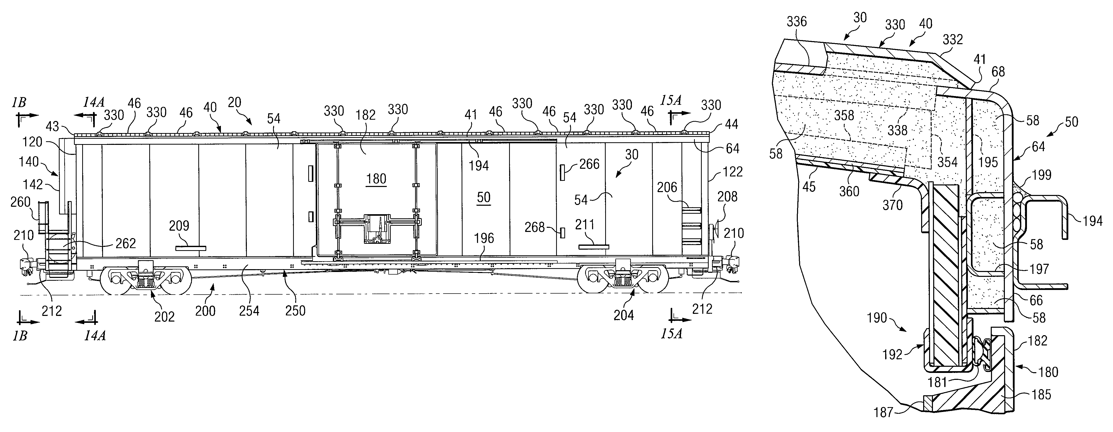
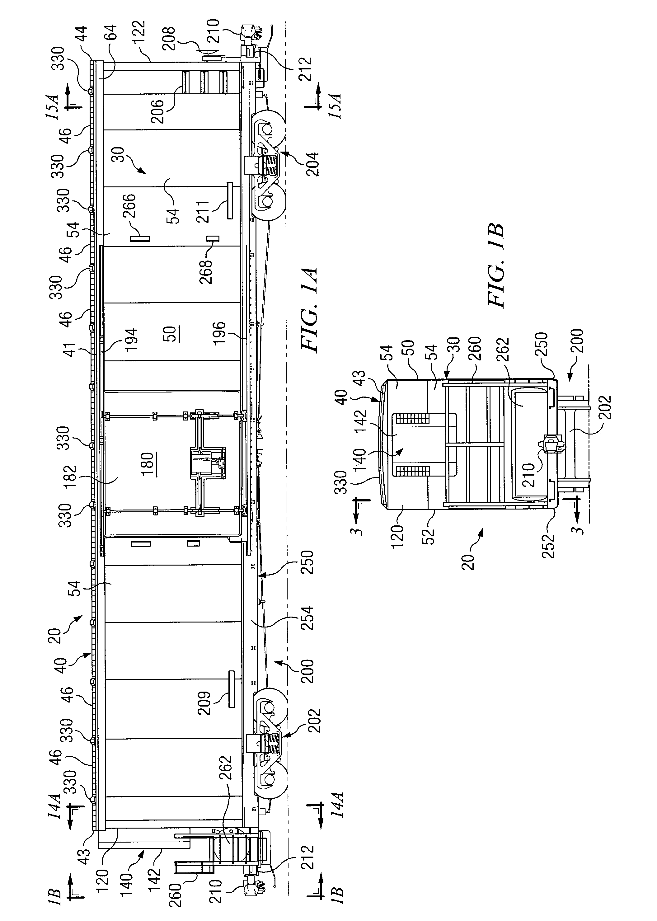
[0042]Various aspects of the present invention will be described with respect to temperature controlled railway car 20. However, the present invention is not limited to temperature controlled railway cars. For example, various features of the present invention may be satisfactorily used to form insulated boxcars and any other type of freight car or railway car having sidewall assemblies and / or endwall assemblies mounted on a railway car underframe.

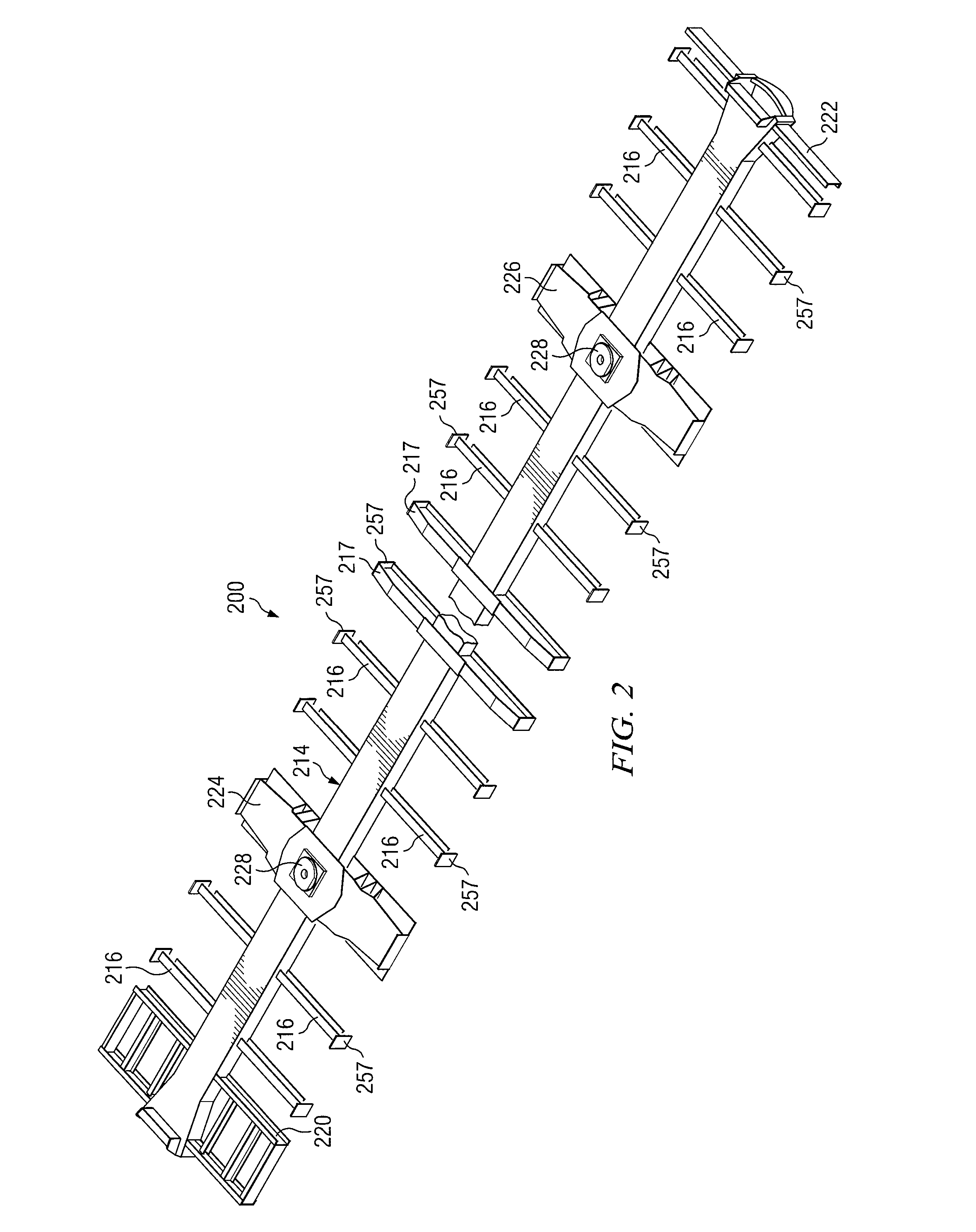
[0043]Temperature controlled railway car 20 incorporating teachings of the present invention is shown in FIGS. 1A and 1B with composite box structure 30 mounted on railway car underframe 200. As discussed later in more detail, temperature controlled railway car 20 may include temperature control system 140 and airflow management system...


PUM


Abstract

A composite box structure mounted on and attached to a railway car underframe to form a temperature controlled railway car. The composite box structure defined in part by an exterior metal surface, interior side stakes and at least one layer of fiber reinforced material attached to the side stakes. Insulating material may be disposed between the side stakes, the exterior metal surface and the at least one fiber reinforced layer of fiber reinforced material. The insulating materials provide resistance to heat transfer between the interior and the exterior of the composite box structure. A primary floor assembly and a secondary floor assembly may be mounted on the railway car underframe.

Description

RELATED APPLICATION[0001]This application is a Continuation Application of U.S. patent application Ser. No. 11 / 009,128 entitled “Temperature Controlled Railway Car” filed Dec. 10, 2004, now U.S. Pat. No. 7,228,805 which is a Continuation-In-Part Application of U.S. Divisional Application Ser. No. 10 / 424,279 entitled “Temperature Controlled Railway Car” filed Apr. 28, 2003, now U.S. Pat. No. 6,941,875, which claims the benefit of U.S. application Ser. No. 10 / 071,168 entitled “Temperature Controlled Railway Car” filed Feb. 8, 2002, now U.S. Pat. No. 6,575,102, which claims the benefit of U.S. Provisional Application Ser. No. 60 / 267,882 entitled “Temperature Controlled Railway Car” filed Feb. 9, 2001.[0002]This application is related to copending U.S. patent application Ser. No. 10 / 071,165 entitled “Pultruded Panel” filed Feb. 8, 2002; U.S. patent application Ser. No. 10 / 071,173 entitled “Roof Assembly and Airflow Management System for a Temperature Controlled Railway Car” filed Feb. 8...

Claims


Application Information

Patent Timeline
Patent Type & Authority Patents(United States)
IPC IPC(8): B61D17/00
CPCB61D17/005B61D17/045B61D17/12B61D27/0027
Inventor BEERS, ALBERT A.SMITH, STEPHEN W.CRISAFULLI, CHRISTOPHERRICHMOND, SHAUNCRIBBS, RICKY A.
Owner TRINITY IND INC
Why Eureka
Try Eureka