Structure for reducing agent container

Active Publication Date: 2007-04-05
NISSAN DIESEL MOTOR CO
View PDF6 Cites 20 Cited by
  • Summary
  • Abstract
  • Description
  • Claims
  • Application Information

AI Technical Summary

Benefits of technology

[0010] Preferably, the canopy is comprised of a metal plate with good heat transfer characteristics. Thus, heat is easily transferred from the inlet port of the heating medium to the canopy, so that the canopy can be warmed up in a short time and evenly, and the surroundings of the supply port and the return port of the liquid reducing agent are heated. Therefore, freezing of the liquid reducing agent existing around the supply port and the return port of the liquid reducing agent can be prevented.
[0011] According to the structure for a reducing agent container in accordance with the present invention, when the water level indicator and the densitometer fitted to the reducing agent container are to be inspected and maintained, the canopy which closes the opening provided in the upper surface of the container body is dismounted from the container body, and the heat exchanger is drawn out upwards without causing any interference of the heat exchanger wit

Problems solved by technology

However, even if the densitometer and the water level indicator are detachably fitted to the reducing agent container, if their attachment and detachment requires a lot of time and labor, inspection and maintenance takes time, so that the cost for maintaining the function of the exhaust gas purificatio

Method used


Image

  • Structure for reducing agent container
  • Structure for reducing agent container
  • Structure for reducing agent container

Examples


Example

[0019] Hereunder is a detailed description of the present invention with reference to the accompanying drawings.

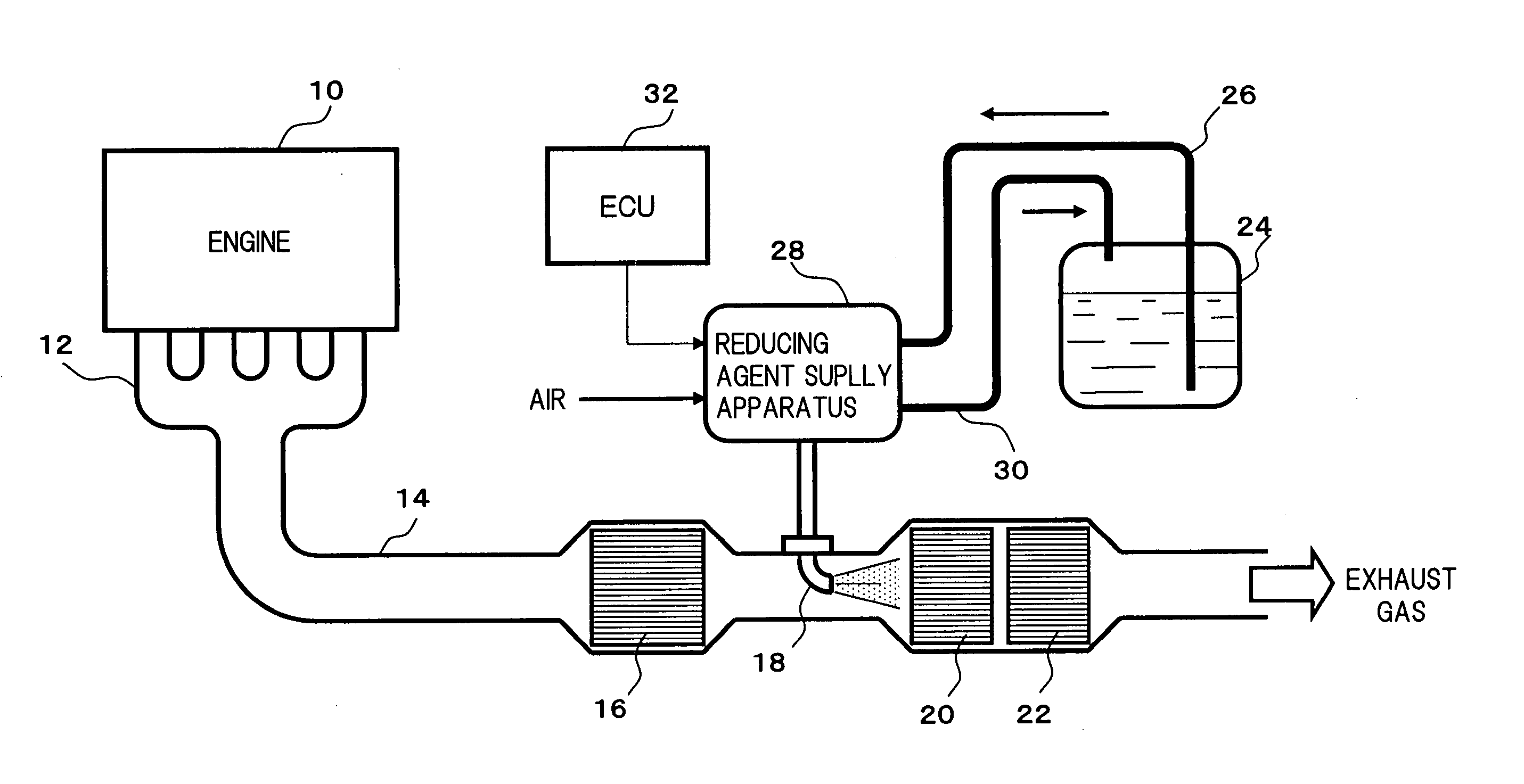
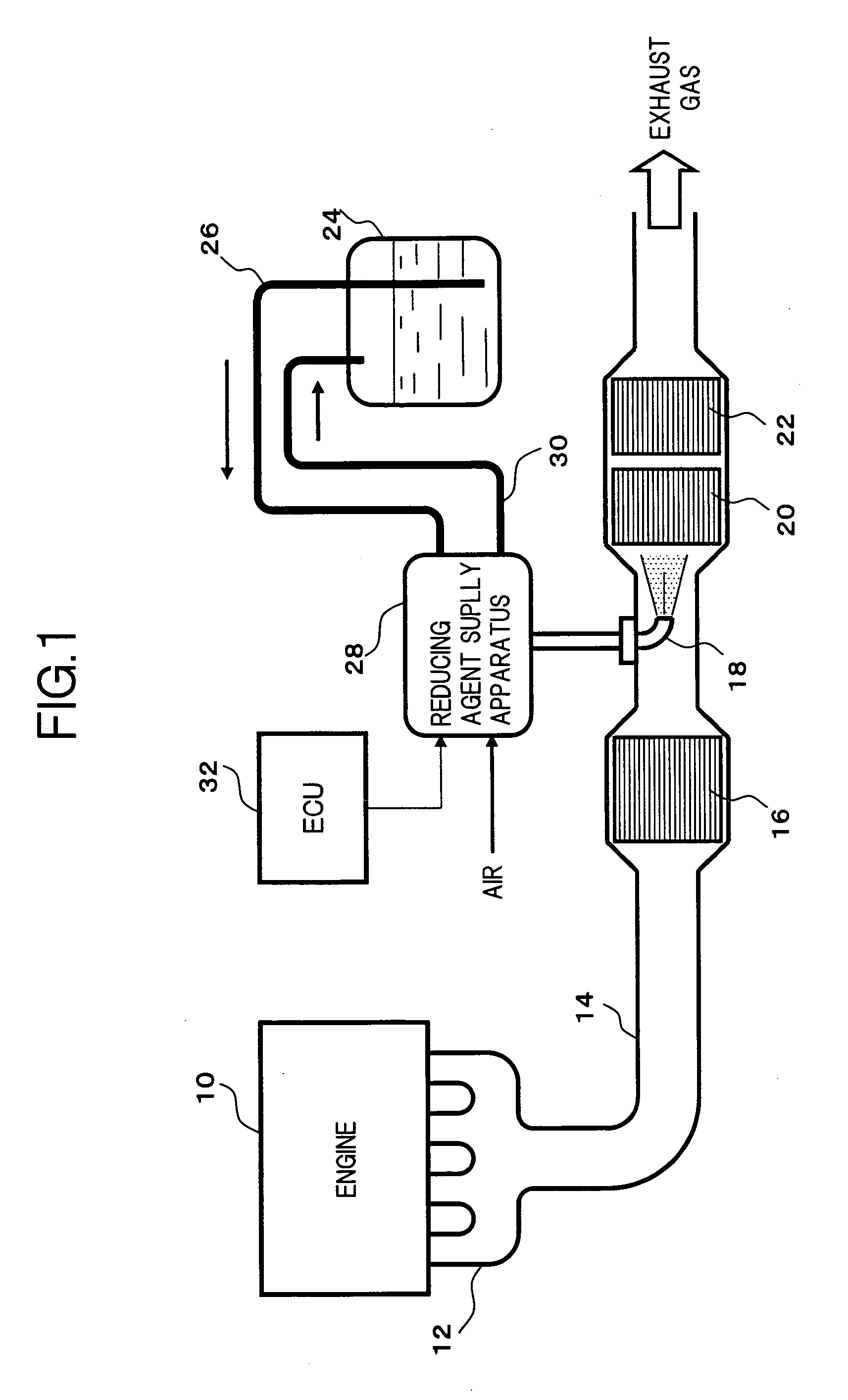
[0020]FIG. 1 is an overall block diagram of an exhaust gas purification apparatus which uses a urea aqueous solution as a liquid reducing agent, and which purifies the NOx contained in engine exhaust gas by a reduction catalyst reaction.

[0021] An exhaust pipe 14 connected to an exhaust gas manifold 12 of an engine 10 is respectively provided along the direction of the exhaust gas flow with: an oxidation catalytic converter 16 which oxidizes nitrogen monoxide (NO) to nitrogen dioxide (NO2); an injection nozzle 18 which injects a urea aqueous solution; a NOx reduction catalytic converter 20 which reduction purifies NO by ammonia obtained by hydrolysis of the urea aqueous solution; and an ammonia oxidation catalytic converter 22 which oxidizes the ammonia which has passed through the NOx reduction catalytic converter 20. Furthermore, the urea aqueous solution stored in a re...


PUM

PropertyMeasurementUnit
Diameteraaaaaaaaaa
Concentrationaaaaaaaaaa
Structureaaaaaaaaaa

Abstract

A canopy is removably secured to the container body, is respectively fitted with: a base of a water level indicator for detecting a remaining amount of liquid reducing agent; a base of a densitometer for detecting a concentration of a liquid reducing agent; and a heat exchanger which surrounds detection portions respectively suspended from the bases of the water level indicator and the densitometer, and through which is circulated engine coolant, to perform heat exchange with the liquid reducing agent, and a supply port and a return port for the liquid reducing agent are respectively formed in the canopy. The water level indicator, the densitometer, the heat exchanger, and the supply port and the return port for the liquid reducing agent are formed integrally with the canopy, so that the water level indicator and the densitometer can be dismounted together with the canopy at the same time.

Description

[0001] This application is a continuation of PCT / JP2005 / 003934, filed on Mar. 8, 2005.BACKGROUND OF THE INVENTION [0002] 1. Field of the Invention [0003] The present invention relates to a structure for a reducing agent container which stores a liquid reducing agent used in an exhaust gas purification apparatus which reduces and purifies nitrogen oxide (NOx) in exhaust gas. In particular, the invention relates to technology which simplifies inspection and maintenance of a densitometer and a water level indicator which respectively detect the concentration and remaining amount of liquid reducing agent. [0004] 2. Description of the Related Art [0005] As a catalytic conversion system for removing NOx contained in engine exhaust gas, there is proposed an exhaust gas purification apparatus disclosed in Japanese Unexamined Patent Publication No. 2000-27627. This exhaust gas purification apparatus injection supplies liquid reducing agent in a necessary amount corresponding to engine operat...

Claims


Application Information

Patent Timeline
IPC IPC(8): C21D11/00B01D53/94F01N3/00F01N3/08F01N3/20F01N3/24G01F23/00G01F23/26
CPCB01D53/9431B01D2251/2062F01N3/2066F01N2610/02F01N2610/10F01N2610/1406F01N2610/148F01N2610/1466Y02T10/24Y02T10/12
Inventor OSAKU, YASUSHIKONDOU, TOSHIOFUKUDA, KIYOSHI
Owner NISSAN DIESEL MOTOR CO
Why Eureka
Try Eureka