Method of mitigating the effects of damage in an article

a technology of damage and article, applied in the field of treating articles, can solve the problems that fatigue cracks cannot initiate nor grow to failure, and achieve the effects of reducing the cost of implementation, and reducing the risk of damage to metals

Inactive Publication Date: 2008-06-05
SURFACE TECH HLDG
View PDF3 Cites 14 Cited by
  • Summary
  • Abstract
  • Description
  • Claims
  • Application Information

AI Technical Summary

Benefits of technology

[0009]The present invention is directed to a method, which fulfills the need for a low cost, easily implemented method to mitigate damage to metallic, ceramic and intermetallic articles to increase fatigue life, decrease maintenance and inspection costs, and improve equipment readiness. The method comprises introducing compressive residual stresses in damaged or potentially damaged areas of the article to mitigate the effects of damage and the risk of fatigue failure. The induced compressive stress extends beneath the surface of the article to a depth greater than the penetration depth of the damage mechanism such that the tips of the notch-like features caused by the damage are in compression. The method utilizes the stress concentration factor associated with the tip of a damage-induced notch-like feature combined with sufficient induced residual compressive stress at the depth of the notch tip to exceed the applied tension in service such that the crack tip remains in higher compression than the surrounding material. If the local residual compression at the fatigue critical location where notch-like damage may occur or at an existing notch tip is greater than the applied tension, then the notch tip will always be in compression with a magnitude equal to the stress concentration factor of the notch times the net compression. Using this method, the notch-like feature always remains in compression, and fatigue cracks can neither initiate nor grow to failure. As a result, the induced compressive stress need only exceed the applied tensile stresses and not necessarily the applied tensile stresses multiplied by the stress intensity factor.
[0016]In another embodiment, the magnitude of the induced compressive residual stress distribution at the tip of the damage notch-like feature completely offsets the applied tensile stresses acting on the notch-like feature such that the tip of the feature remains in compression during operational loading.
[0017]In another embodiment, the magnitude of the induced compressive residual stress distribution is minimized thereby reducing the associated equilibrating tension and minimizing distortion of the article.

Problems solved by technology

Using this method, the notch-like feature always remains in compression, and fatigue cracks can neither initiate nor grow to failure.

Method used


Image

  • Method of mitigating the effects of damage in an article
  • Method of mitigating the effects of damage in an article
  • Method of mitigating the effects of damage in an article

Examples


example 1

No Mitigation of Applied Stresses

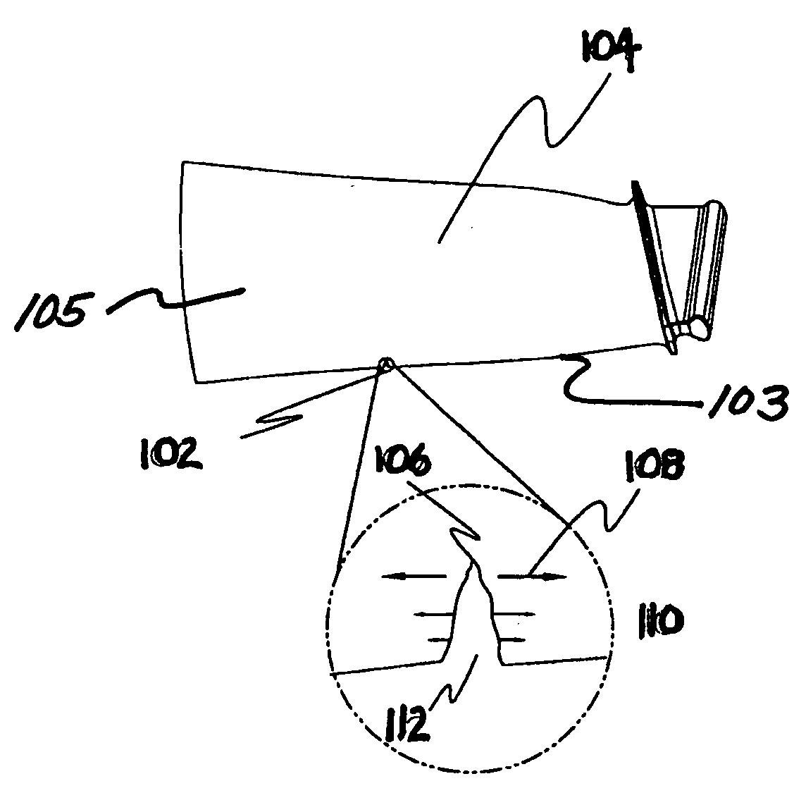
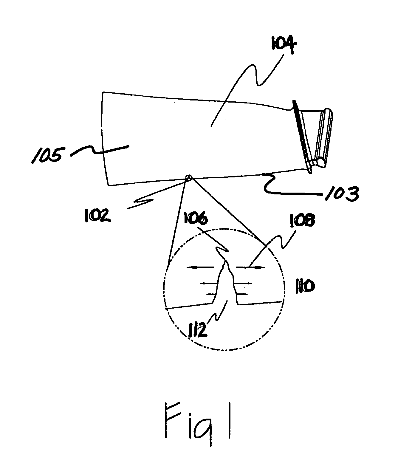
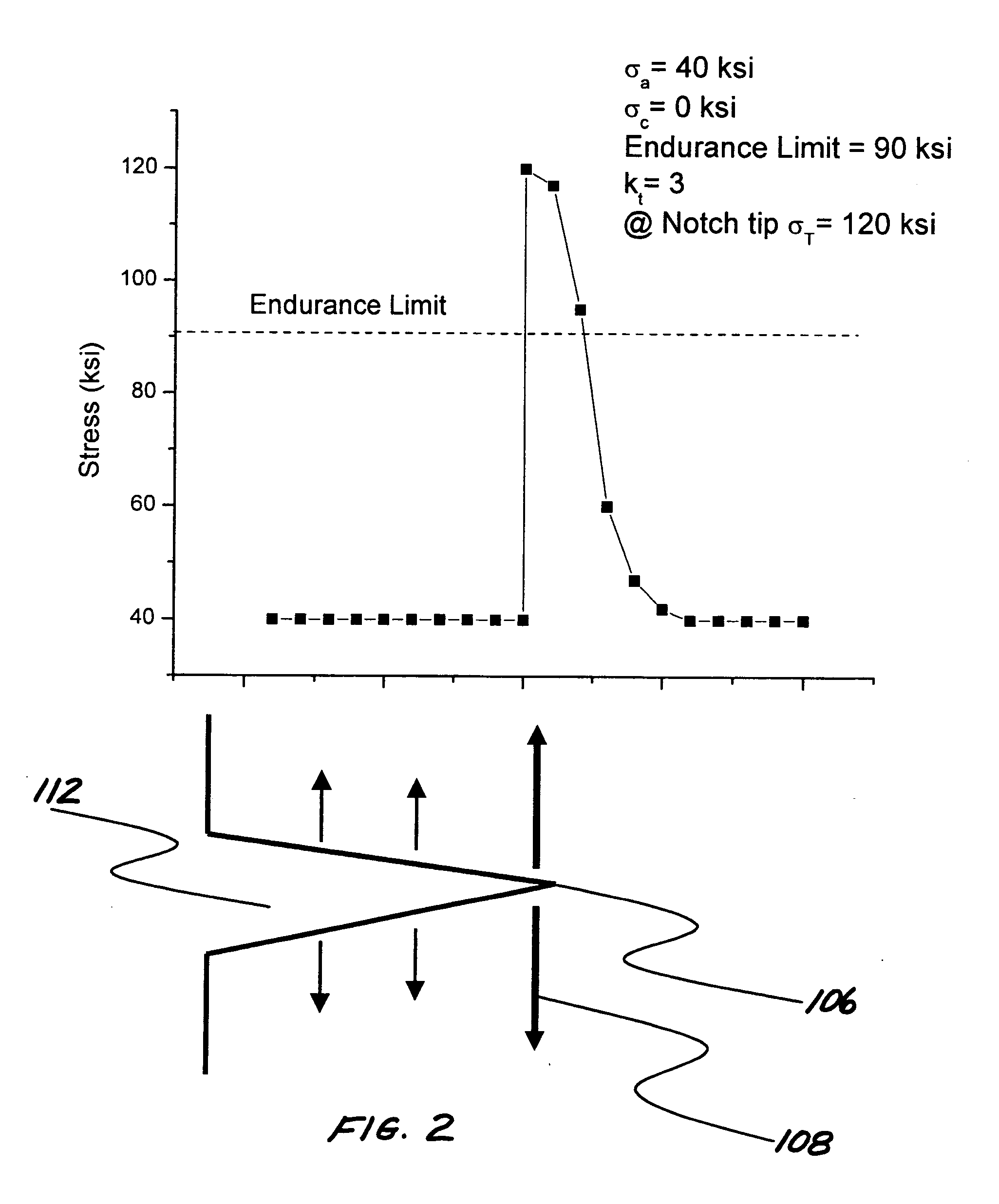
[0027]Referring to FIG. 1, an article 104, such as a titanium alloy compressor blade, has a V-shaped FOD notch-like feature 112. The notch-like feature 112 has a stress intensity factor of kt=3. The endurance limit for the article is 90 ksi. The location of the notch-like feature 112, prior to damage, is subject to an applied stress of 40 ksi. After damage, the area 102 at the base of the FOD notch-like feature 112 is subject to a total stress (σT) equal to the applied stress (σa) multiplied by the stress intensity factor (kt). Therefore, after damage, the total stress (σT) 108 acting on the notch tip 106 is 120 ksi. Because the stress 108 acting on the notch tip 106 exceeds the endurance limit for the material (90 ksi), the article 104 would have a significantly reduced fatigue life and ultimately fail as a result of fatigue cracks nucleating out of the notch-like feature 112. The magnitude of stresses acting along the notch-like feature 112 is grap...

example 2

Complete Mitigation of Applied Stresses

[0035]The notch-like feature 112 discussed in Example 1 is now treated according to the method of the present invention and a residual compressive stress distribution 116 is introduced around the notch tip 106. The magnitude of the compressive residual stress distribution 116 is −50 ksi. The total stress 114, σT, acting on the notch tip 106 during service is:

σT=(σz+σc)×kt

where σa is the maximum applied stress (40 ksi), σc is the magnitude of the residual compressive stress distribution 116 at the notch tip 106 (−50 ksi), and kt=3 is the stress intensity factor for the notch configuration. Therefore, after treatment to induce the residual compressive stress, the total stress 114 acting on the notch tip 106 during service of the metallic article is −30 ksi. Thus the notch-like feature 112 remains in compression even under the maximum tensile applied loading conditions. Because the stress 114 acting on the notch tip 106 is less than the endurance...

example 3

Partial Mitigation of Applied Stresses

[0039]The notch-like feature 112 discussed in Example 1 is now treated according to the method of the present invention and a residual compressive distribution is introduced around the notch tip 106. The induced compressive residual stress is −30 ksi. The total stress 108, σT, acting on the notch tip 106 during service is:

σT(σa+σc)×kt

where σa is the maximum applied stress (40 ksi), σc is the magnitude of the residual compressive stress distribution (−30 ksi), and kt=3 is the stress intensity factor for the notch-like feature 112 configuration. Therefore, the total stress 108 acting on the notch tip 106 after treatment is tensile, +30 ksi. As this value is much less than the endurance limit of the material (90 ksi) the risk of fatigue cracks nucleating from the notch-like feature 112 is effectively mitigated. Example 3 is graphically illustrated in FIG. 5.

[0040]The surface treatment method of the present invention can be used to treat a variety ...


PUM

PropertyMeasurementUnit
stress concentrationaaaaaaaaaa
compressive residual stressaaaaaaaaaa
compressive residual stress distributionaaaaaaaaaa

Abstract

A method of mitigating the effects of damage to a metallic, ceramic, or intermetallic article through the introduction of compressive residual stresses taking into account the effects of the stress concentration factor associated with a damage notch under compression. A layer of compressive residual stress is introduced into the surface of the article to a depth greater than the depth to which damage, such as corrosion pitting or foreign object damage, extends into the surface of the part. The induced compressive residual stresses improve the fatigue and stress corrosion cracking performance of the article while the stress concentrating properties associated with a damage notch under compression prevents cracks from initiating from within the notch under applied loads.

Description

[0001]This application claims the benefit of U.S. Provisional Application No. 60 / 854,040, filed Oct. 24, 2006.BACKGROUND OF THE INVENTION[0002]The present invention relates to a method of treating an article and, more particularly, to a method of inducing compressive residual stress in areas of an article subject to localized surface damage, such as foreign object damage, fretting, or corrosion, to mitigate failures caused by these mechanisms.[0003]Articles made from metallic, ceramic and intermetallic materials may be subject to localized surface damage, including foreign object damage (FOD), fretting, and corrosion pitting, each of which adversely impacts the fatigue strength of the article. Each of these damage mechanisms produces indentations, pits, cracks, or similar notch-like features that serve as stress concentrators or stress risers such that, as the article experiences an applied stress, the material at the tip of the notch-like feature experiences greater stress than und...

Claims


Application Information

Patent Timeline
Patent Type & Authority Applications(United States)
IPC IPC(8): B23P6/00
CPCB23P6/002B23P9/00C21D7/00Y10T29/49748C21D7/08C21D10/005Y10T29/49723C21D7/06
Inventor PREVEY, PAUL S.
Owner SURFACE TECH HLDG
Why Eureka
Try Eureka