Brake controller

A brake control and control panel technology, applied in the direction of brakes, brake components, control valves and air release valves, etc., can solve the problems of control panel solenoid valve heat dissipation, complex piping connections, large installation space, etc. The effect of reducing, securing distance, and reducing the influence of heat dissipation

Inactive Publication Date: 2006-06-28
NABLESCO CORP
View PDF1 Cites 15 Cited by
  • Summary
  • Abstract
  • Description
  • Claims
  • Application Information

AI Technical Summary

Problems solved by technology

[0003] In the above-mentioned conventional brake control device, since the relay valve and the emergency load-adapting automatic adjustment valve are arranged separately as different structural parts, the piping connection between them becomes complicated. In addition, Since there are also solenoid valves, control panels, etc., the number of parts is also large, so naturally there is a problem that a large installation space is required.
In addition, as in Patent Document 1 figure 2 As shown, when a control panel is arranged in the open space above the solenoid valve inside the waterproof cover, there is a disadvantage that the control panel on the upper side is easily affected by heat radiation from the solenoid valve.

Method used


Image

  • Brake controller
  • Brake controller
  • Brake controller

Examples


no. 1 example

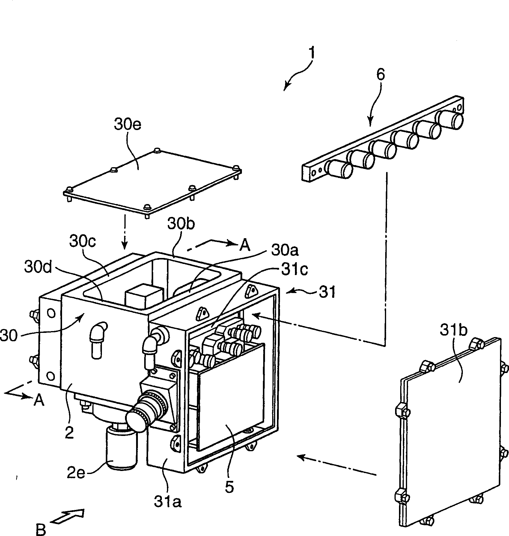
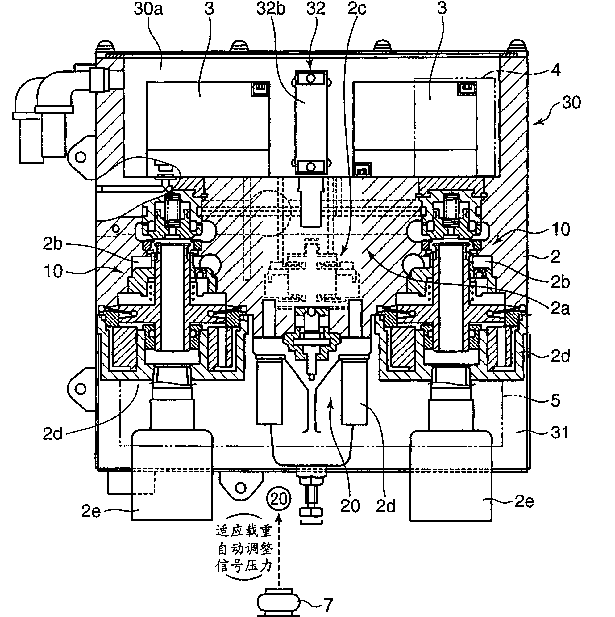
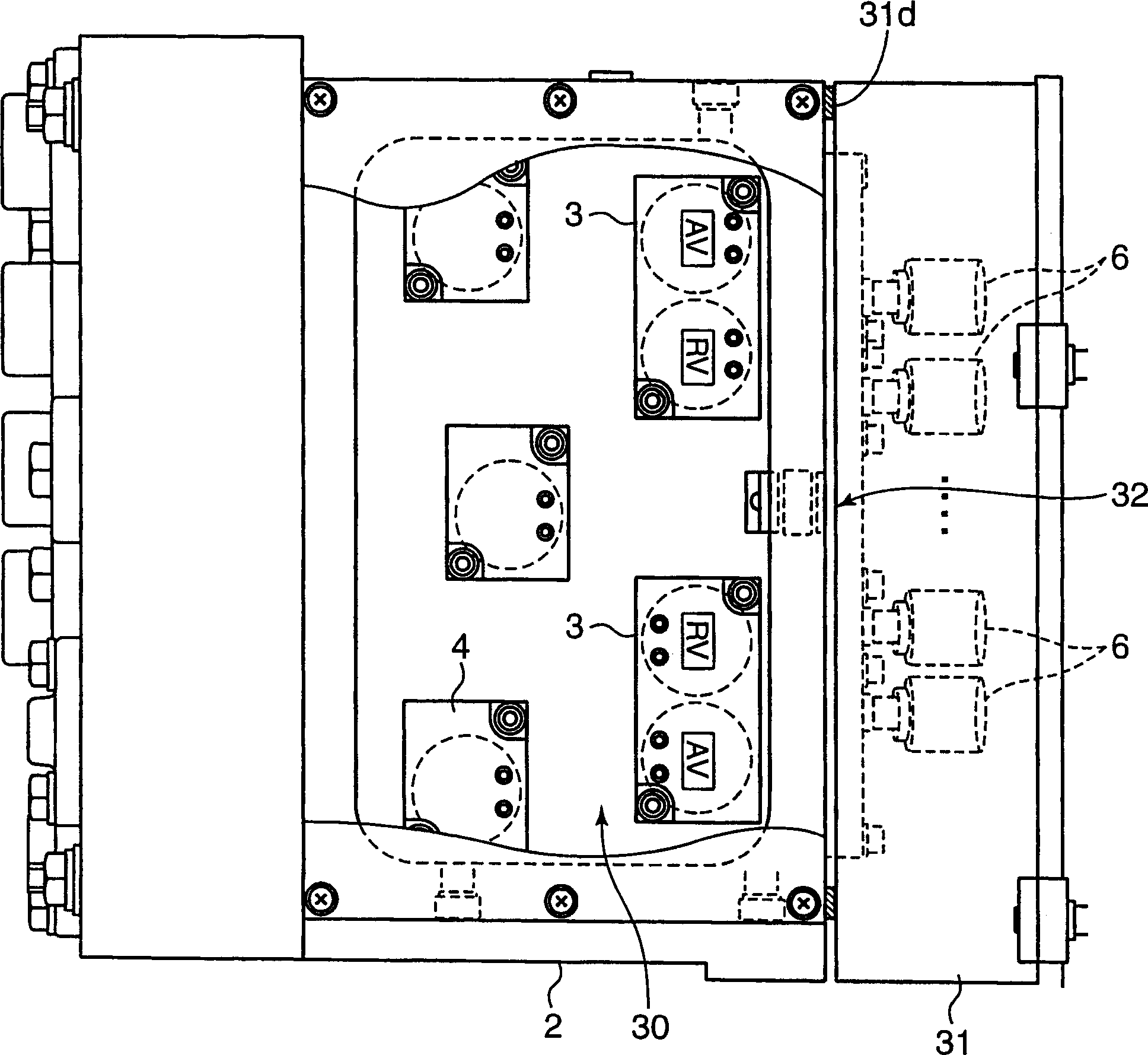
[0030] figure 1 is an exploded perspective view showing the brake control device according to the first embodiment of the present invention, figure 2 It is a longitudinal section view of the brake control device ( figure 1 The profile of the A-A line), image 3 is the brake control device with figure 1 The plan view (partial section) when the B direction is the front, Figure 4 is a schematic diagram showing a control object of the brake control device.

[0031] In a vehicle 100 provided with this brake control device 1, a total of four wheel axles 103, 103 are provided at the front and rear of two bogies 101, 101 provided at the front and rear of the vehicle. A total of 12 ( Figure 4Indicates 4) brake cylinders 110. In the first embodiment, the control device 1 is structured such that it is provided at the rear with respect to three brake cylinders 110 as a set provided on the front wheel axle and the left and right wheels of one bogie. Three sets of brake cylinder...

no. 2 example

[0041] Figure 6 is an exploded perspective view showing a brake control device according to a second embodiment of the present invention, Figure 7 is a front view showing the brake control device, Figure 8 It is a plan view of the same brake control device. In addition, in this second embodiment, it is possible to choose between using different relay valves to actuate a group of brake cylinders on the front side of the bogie and a group of brake cylinders on the rear side of the bogie and using a common relay valve. The valve activates the brake cylinder. Additionally, with Figure 1 to Figure 5 The same symbols are used for the same parts.

[0042] In this brake control device 1A, the valve main body unit 40 includes a substantially rectangular parallelepiped block 40 a having an automatic load-adaptive adjustment valve and a relay valve and their input and output lines inside, and a relay valve and its input pipes inside. A substantially rectangular parallelepiped-sh...

no. 3 example

[0048] Figure 9 is an exploded perspective view showing a brake control device according to a third embodiment of the present invention, Figure 10 It is a plan view showing the state where the two storage parts are turned relative to the valve body unit. Additionally, with Figure 1 to Figure 5 The same symbols are used for the same parts.

[0049] This brake control device 1B has a structure in which a rotating shaft 43 is provided in the vertical direction on a valve body unit 40B and an accommodating portion 41 arranged on the upper surface thereof, and the accommodating portion integrated like the second embodiment can be integrated. 41 and 42 rotate around the rotation shaft 43 with respect to the valve body unit 40B, and the storage portion 42 can be formed into a state of covering the side surface of the valve body unit 40B and a state of exposing the side surface of the valve body unit 40B by rotation.

[0050]This valve body unit 40B is different from the second ...


PUM


Abstract

PROBLEM TO BE SOLVED: To realize miniaturization and to constitute a control panel so as to hardly receive influence of heat release from a solenoid valve.

SOLUTION: The brake control device is provided with a regular use solenoid valve 3 in common use for feeding a control pressure according to an electric signal; a relay valve 10 for feeding a brake pressure to a brake cylinder based on the control pressure; a variable load valve 20 for feeding an emergency control pressure based on the variable load signal pressure from an air spring 7; an emergency solenoid valve 4 for feeding the emergency control pressure to the relay valve 10 according to the electric signal; and the control panel 5 for controlling a voltage applied to the regular use solenoid valve 3 and the emergency solenoid valve 4. The device has a valve body unit 2 installed with the relay valve 10, the variable load valve 20 and the input/output conduit in the inside. The regular use solenoid valve 3 and the emergency solenoid valve 4 are provided on an upper surface side on the outer side of the valve body unit 2 and the control board 5 is provided on a side surface side of the outer side of the valve body unit 2.

COPYRIGHT: (C)2006,JPO&NCIPI

Description

technical field [0001] The present invention relates to a brake control device for driving and controlling a brake cylinder provided corresponding to a wheel or the like of a railway vehicle in accordance with the operation of a brake operation unit. Background technique [0002] At present, in the brake control device of railway vehicles, as a common brake system, there is a control panel that outputs a brake command signal (electrical signal), and a brake command pressure corresponding to the brake command signal (electrical signal) is provided. (Air pressure) output solenoid valve, the brake command pressure output by the solenoid valve is used as the control pressure, and the capacity is expanded based on the control pressure and output to the relay valve of the brake cylinder. In addition, it is used as an emergency brake The system has a load-adaptive automatic adjustment valve that expands its capacity according to the total weight of the vehicle including the passeng...

Claims


Application Information

Patent Timeline
Patent Type & Authority Applications(China)
IPC IPC(8): B60T15/36B60T8/18
CPCB60T8/17B60T8/18B60T8/341B60T15/36
Inventor 赤松修山中雅民森本和宪
Owner NABLESCO CORP
Why Eureka
Try Eureka