
Positioning method of ink jet printing equipment and ink-jet printing head

A technology of inkjet printing and positioning method, which is applied in the direction of printing and printing devices, and can solve the problems of scratching the substrate 108, tailing of inkjet droplets, and inability of inkjet droplets 110 to fall on a predetermined position, etc.

Inactive Publication Date: 2004-06-16
RITDISPLAY
View PDF0 Cites 14 Cited by
  • Summary
  • Abstract
  • Description
  • Claims
  • Application Information

AI Technical Summary

Problems solved by technology

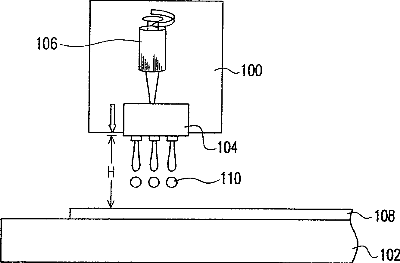
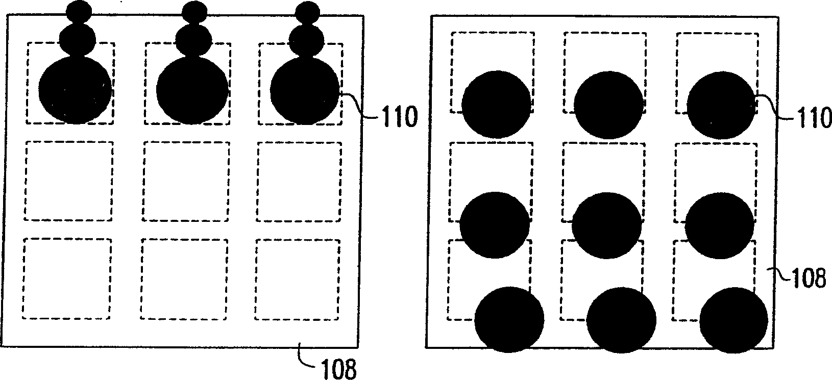
Conversely, if figure 2 As shown on the left side of , when the distance from the inkjet head 104 to the substrate 108 is too far, the inkjet droplet 110 cannot land on the predetermined position
In addition, if the distance between the inkjet head 104 and the substrate 108 is too short, there may even be a risk of scratching the substrate 108 or causing damage to the inkjet head 104
[0011] It is known that adjusting the distance between the inkjet head and the substrate can only be manually fine-tuned by micrometers, but this cannot accurately control the thickness of the substrate after each replacement of the inkjet head (with the same specification or a different specification) When changing, the distance between the inkjet head and the substrate will cause the inkjet droplets to trail or fail to fall on the predetermined position
In addition, it is known that the use of manual fine-tuning will increase the time required for the process

Method used


Image

  • Positioning method of ink jet printing equipment and ink-jet printing head
  • Positioning method of ink jet printing equipment and ink-jet printing head
  • Positioning method of ink jet printing equipment and ink-jet printing head

Examples


no. 1 example

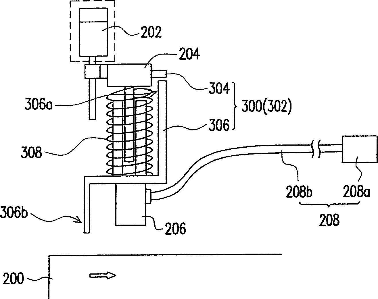
[0061] image 3 is a schematic diagram of an inkjet printing device according to a first embodiment of the present invention. Please refer to image 3 , the inkjet printing device of this embodiment is mainly composed of a carrier platform 200 , a servo motor 202 , a carrier 204 , a height sensing device 300 , an inkjet head 206 and a feeding device 208 . Wherein, the carrier platform 200 is suitable for carrying a substrate (not shown); the carrier 202 is disposed above the carrier platform 200; the servo motor 202 is connected to the carrier 204, and the servo motor 202 can control the movement of the carrier 204, thereby adjusting The distance from the carrier 204 to the carrying platform 200; the height sensing device 300 is configured on the carrier 204; the inkjet head 206 is configured on the carrier 204; and the feeding device 208 is connected with the inkjet head 206 to provide inkjet The ink solution is fed into the inkjet head 206 .

[0062] The height sensing de...

no. 2 example

[0070] Figure 7 It is a schematic diagram of an inkjet printing device according to a second embodiment of the present invention. Please refer to Figure 7 , the inkjet printing equipment of this embodiment is similar to the first embodiment, but the difference is that the height sensing device 400 of this embodiment is a non-contact height sensing device 402, and this contact height sensing device 402 is for example It is composed of a first fixed distance sensor 404 and a second fixed distance sensor 406 . Wherein, the first fixed distance sensor 404 is configured on the carrying platform 200 , for example, and the second fixed distance sensor 406 is configured on the carrier 204 , for example. In addition, the non-contact height sensing device 402 is, for example, a laser sensor or the like.

[0071] Figure 7 to Figure 10 It is a schematic flow chart of positioning the inkjet head according to the second embodiment of the present invention. Please also refer to Fig...


PUM


Abstract

An ink-jet printing apparatus comprising mainly a carrying platform, a servo-motor, a carrying member, a height sensing apparatus, an ink-ejecting head and a feed apparatus, wherein the carrying platform is adapted to carry a base plate, the carrying member is arranged on top of the carrying platform, the servo-motor is connected with the carrying member, and the servo-motor can control the movement of the carrying member, thus regulating the distance between the carrying member and the carrying platform, the height sensing apparatus is arranged on the carrying member, and the feed apparatus is connected with the ink-jet head.

Description

technical field [0001] The present invention relates to an inkjet printing device and a positioning method for an inkjet head, and in particular to an inkjet printing device with a height sensor and a servomotor and the above inkjet A positioning method for an inkjet head in a printing device. Background technique [0002] The information and communication industry has become the mainstream industry today, especially the development of various portable communication display products, and the flat panel display is the communication interface between people and information, so its development is particularly important. The technologies currently used in flat-panel displays mainly include the following: plasma display (Plasma Display Panel, PDP), liquid crystal display (LiquidCrystal Display, LCD), inorganic electroluminescent display (Electro-luminescentDisplay), light-emitting diode (Light Emitting Diode, LED), Vacuum Fluorescent Display (Vacuum Fluorescent Display), Field E...

Claims


Application Information

Patent Timeline
IPC IPC(8): B41J29/38
Inventor 韩于凯萧夏彩段继贤
Owner RITDISPLAY
Learn More