Structure for reducing agent container

a technology of reducing agent and container, which is applied in the direction of volume measurement, mechanical element fluid pressure measurement, blast furnace, etc., can solve the problems of engine operation with insufficient high cost of maintaining the function of exhaust gas purification apparatus, etc., and achieves good heat transfer characteristics, reduced man hours, and uniform heating in a short time and evenly.

Active Publication Date: 2009-06-09
NISSAN DIESEL MOTOR CO
View PDF17 Cites 20 Cited by
  • Summary
  • Abstract
  • Description
  • Claims
  • Application Information

AI Technical Summary

Benefits of technology

[0008]Therefore, taking into consideration the above problems up to now, an object of the present invention is to provide a structure for a reducing agent container in which the labor necessary for inspection and maintenance may be reduced by enabling simple removal and attachment of the densitometer and the water level indicator from the reducing agent container.
[0010]Preferably, the canopy is comprised of a metal plate with good heat transfer characteristics. Thus, heat is easily transferred from the inlet port of the heating medium to the canopy, so that the canopy can be warmed up in a short time and evenly, and the surroundings of the supply port and the return port of the liquid reducing agent are heated. Therefore, freezing of the liquid reducing agent existing around the supply port and the return port of the liquid reducing agent can be prevented.
[0011]According to the structure for a reducing agent container in accordance with the present invention, when the water level indicator and the densitometer fitted to the reducing agent container are to be inspected and maintained, the canopy which closes the opening provided in the upper surface of the container body is dismounted from the container body, and the heat exchanger is drawn out upwards without causing any interference of the heat exchanger with the container body. At this time, since in addition to the heat exchanger, the bases of the water level indicator and the densitometer are respectively attached to the canopy, these can also be dismounted at the same time. Then, once the inspection and maintenance of the water level indicator and the densitometer has been completed, the heat exchanger is inserted from the opening provided in the upper surface of the container body, and the canopy is secured to the upper surface of the container body. Consequently, since the water level indicator, the densitometer, the heat exchanger, and the supply port and return port of the liquid reducing agent which are integrated with the canopy, are not fixed to the inside wall of the container body, then at the time of inspection and maintenance of the water level indicator and the densitometer, it is not necessary to disassemble the reducing agent container, and hence the man hours can be considerably reduced.

Problems solved by technology

However, even if the densitometer and the water level indicator are detachably fitted to the reducing agent container, if their attachment and detachment requires a lot of time and labor, inspection and maintenance takes time, so that the cost for maintaining the function of the exhaust gas purification apparatus is likely to rise.
Furthermore, if the interval of inspection and maintenance is lengthened in order to avoid an increase in cost required for inspection and maintenance, there is the likelihood of the engine being operated with insufficient function of the exhaust gas purification apparatus.

Method used


Image

  • Structure for reducing agent container
  • Structure for reducing agent container
  • Structure for reducing agent container

Examples


Embodiment Construction

[0019]Hereunder is a detailed description of the present invention with reference to the accompanying drawings.

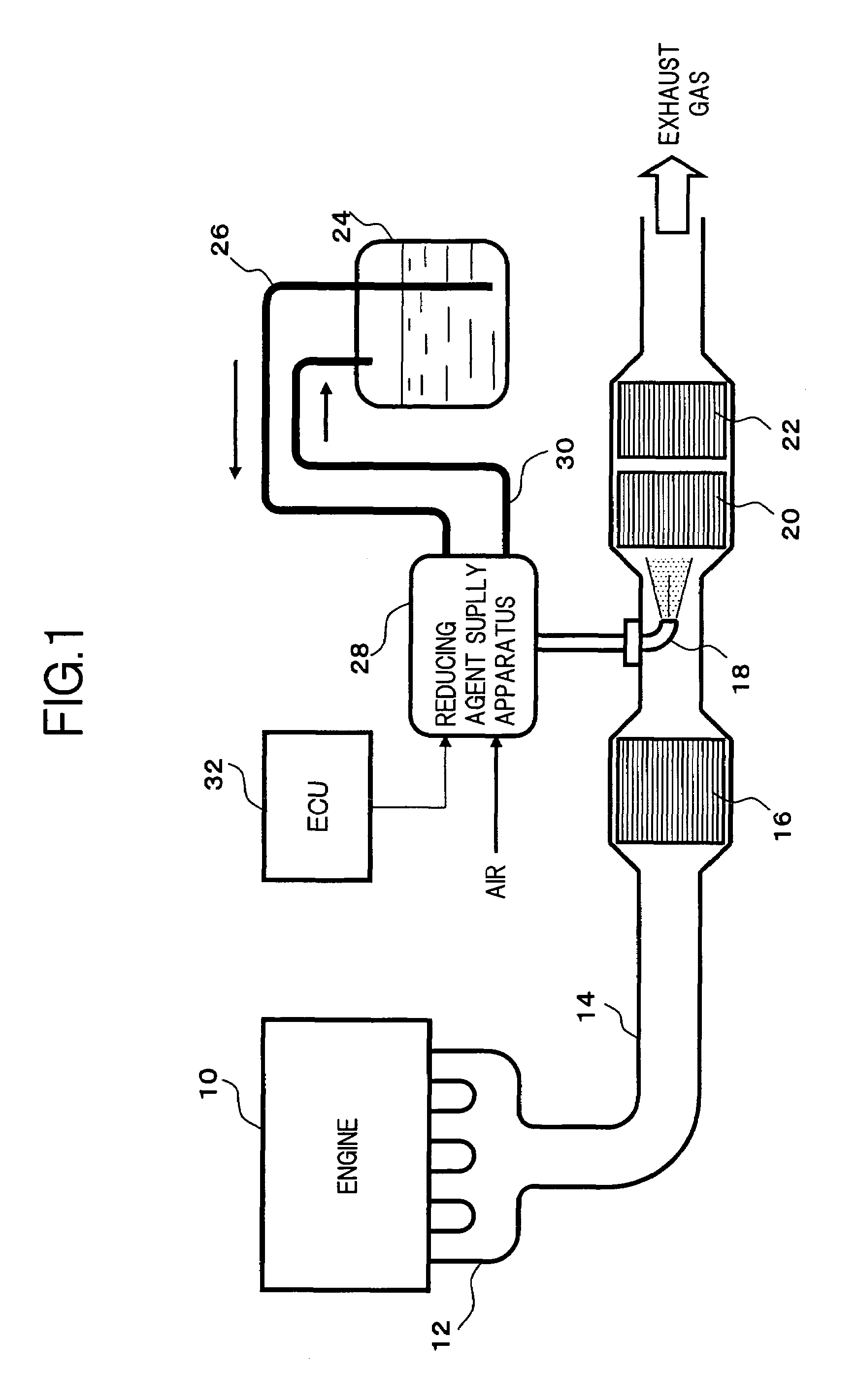
[0020]FIG. 1 is an overall block diagram of an exhaust gas purification apparatus which uses a urea aqueous solution as a liquid reducing agent, and which purifies the NOx contained in engine exhaust gas by a reduction catalyst reaction.

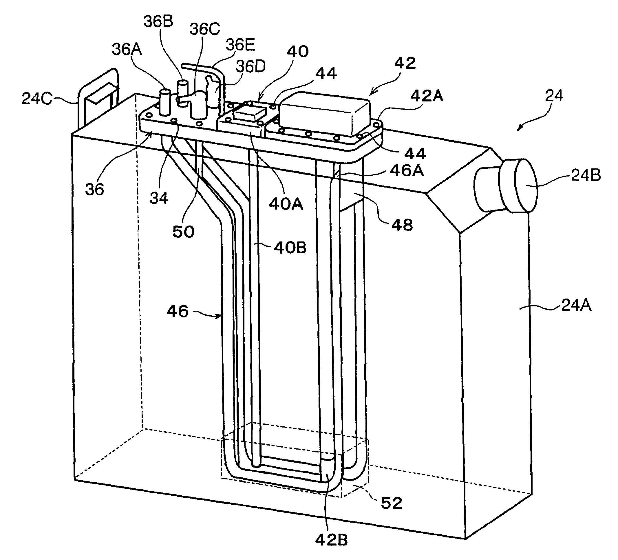
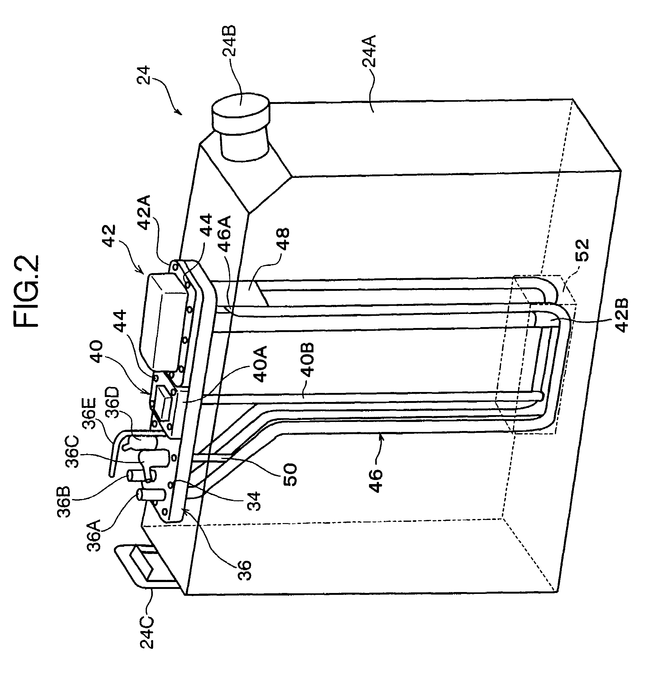
[0021]An exhaust pipe 14 connected to an exhaust gas manifold 12 of an engine 10 is respectively provided along the direction of the exhaust gas flow with: an oxidation catalytic converter 16 which oxidizes nitrogen monoxide (NO) to nitrogen dioxide (NO2); an injection nozzle 18 which injects a urea aqueous solution; a NOx reduction catalytic converter 20 which reduction purifies NO by ammonia obtained by hydrolysis of the urea aqueous solution; and an ammonia oxidation catalytic converter 22 which oxidizes the ammonia which has passed through the NOx reduction catalytic converter 20. Furthermore, the urea aqueous solution stored in a reduci...


PUM

PropertyMeasurementUnit
densityaaaaaaaaaa
diameteraaaaaaaaaa
concentrationaaaaaaaaaa

Abstract

A canopy is removably secured to the container body, is respectively fitted with: a base of a water level indicator for detecting a remaining amount of liquid reducing agent; a base of a densitometer for detecting a concentration of a liquid reducing agent; and a heat exchanger which surrounds detection portions respectively suspended from the bases of the water level indicator and the densitometer, and through which is circulated engine coolant, to perform heat exchange with the liquid reducing agent, and a supply port and a return port for the liquid reducing agent are respectively formed in the canopy. The water level indicator, the densitometer, the heat exchanger, and the supply port and the return port for the liquid reducing agent are formed integrally with the canopy, so that the water level indicator and the densitometer can be dismounted together with the canopy at the same time.

Description

[0001]This application is a continuation of PCT / JP2005 / 003934, filed on Mar. 8, 2005.BACKGROUND OF THE INVENTION[0002]1. Field of the Invention[0003]The present invention relates to a structure for a reducing agent container which stores a liquid reducing agent used in an exhaust gas purification apparatus which reduces and purifies nitrogen oxide (NOx) in exhaust gas. In particular, the invention relates to technology which simplifies inspection and maintenance of a densitometer and a water level indicator which respectively detect the concentration and remaining amount of liquid reducing agent.[0004]2. Description of the Related Art[0005]As a catalytic conversion system for removing NOx contained in engine exhaust gas, there is proposed an exhaust gas purification apparatus disclosed in Japanese Unexamined Patent Publication No. 2000-27627. This exhaust gas purification apparatus injection supplies liquid reducing agent in a necessary amount corresponding to engine operating condi...

Claims


Application Information

Patent Timeline
Patent Type & Authority Patents(United States)
IPC IPC(8): B01J8/00B01D53/94F01N3/00F01N3/08F01N3/20F01N3/24G01F23/00G01F23/26
CPCB01D53/9431F01N3/2066B01D2251/2062F01N2610/02F01N2610/10F01N2610/1406F01N2610/148F01N2610/1466Y02T10/24Y02T10/12
Inventor OSAKU, YASUSHIKONDOU, TOSHIOFUKUDA, KIYOSHI
Owner NISSAN DIESEL MOTOR CO
Why Eureka
Try Eureka