Zero crossing detection of line voltage/current of variable amplitude

a technology of variable amplitude and line voltage, applied in the field of circuits, can solve the problems of unreliability, complex transmission and reception of data, and difficulty in detecting pulses produced, and achieve the effect of adding hysteresis

Inactive Publication Date: 2008-07-01
UNIVERSAL LIGHTING TECHNOLOGIES
View PDF18 Cites 18 Cited by
  • Summary
  • Abstract
  • Description
  • Claims
  • Application Information

AI Technical Summary

Benefits of technology

[0007]Another embodiment of the present invention is directed toward a device for detecting a predetermined phase angle of a received periodic signal having a known waveform but a variable amplitude. The device includes a peak value detector for detecting a peak value of the signal. The peak value detector may be a capacitor that stores the peak signal value of the received signal. A voltage divider divides the peak value of the signal by a ratio of the peak value of the signal for a known amplitude signal to a value of the signal for the known amplitude signal that corresponds to the predetermined phase angle to produce a reference amplitude. A resistive divider may be used to divide the signal and produce the reference amplitude. Alternatively, an average value detector that detects an average value of the received signal may be used and the average value used to calculate the reference amplitude. A reference amplitude detector detects when the periodic signal's amplitude is approximately equal to the reference amplitude. A pulse is produced when the detected signal amplitude is less than the reference amplitude. The device includes means for adding hysteresis to the detector to help with noise immunity. The pulse is used to communicate information from a power line communication controller to electronic ballasts in a lighting system.

Problems solved by technology

The primary disadvantage of using the prior art zero crossing detection circuit is that when the generated pulse width changes due to changes in the input voltage, detection of the pulses produced becomes more difficult and the output of the detection circuit is difficult to interpret.
This makes the transmission and reception of data complicated and unreliable.

Method used


Image

  • Zero crossing detection of line voltage/current of variable amplitude
  • Zero crossing detection of line voltage/current of variable amplitude
  • Zero crossing detection of line voltage/current of variable amplitude

Examples


Embodiment Construction

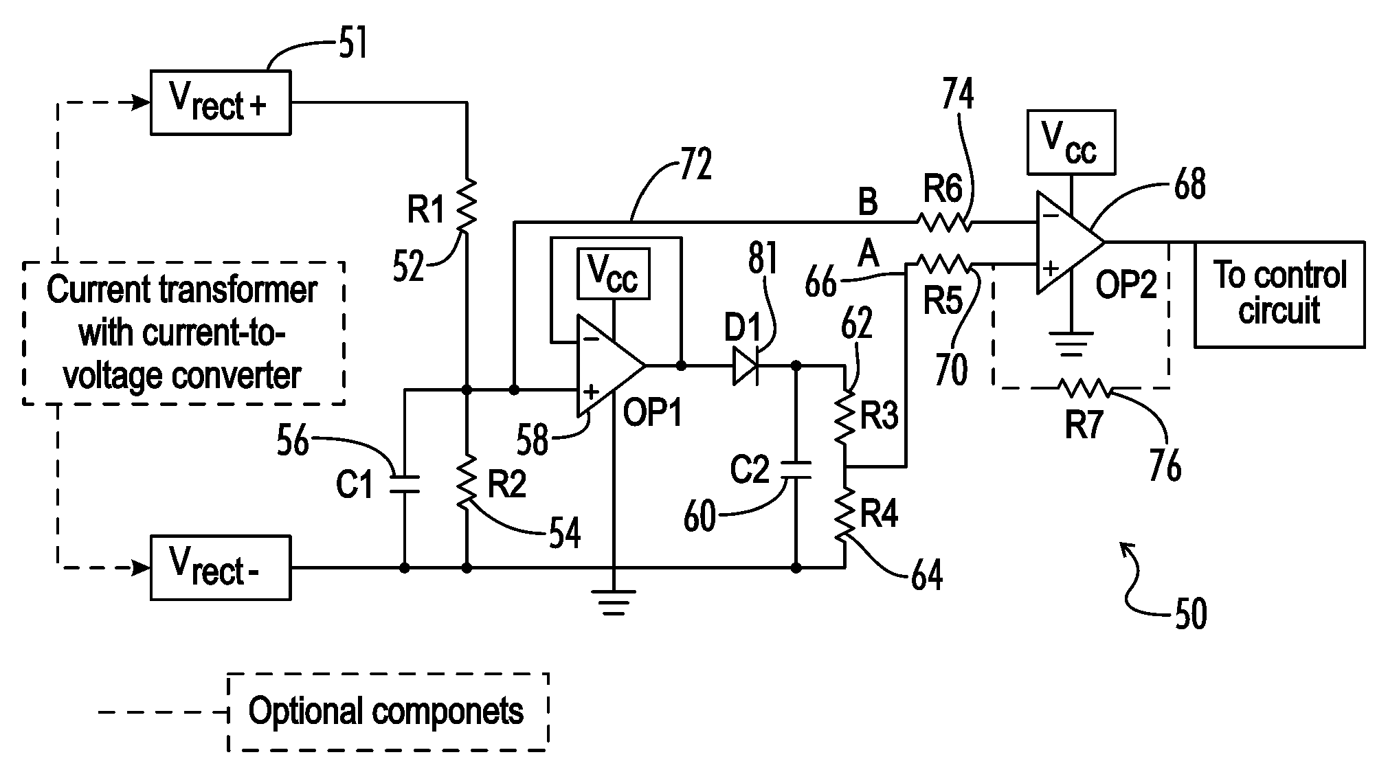
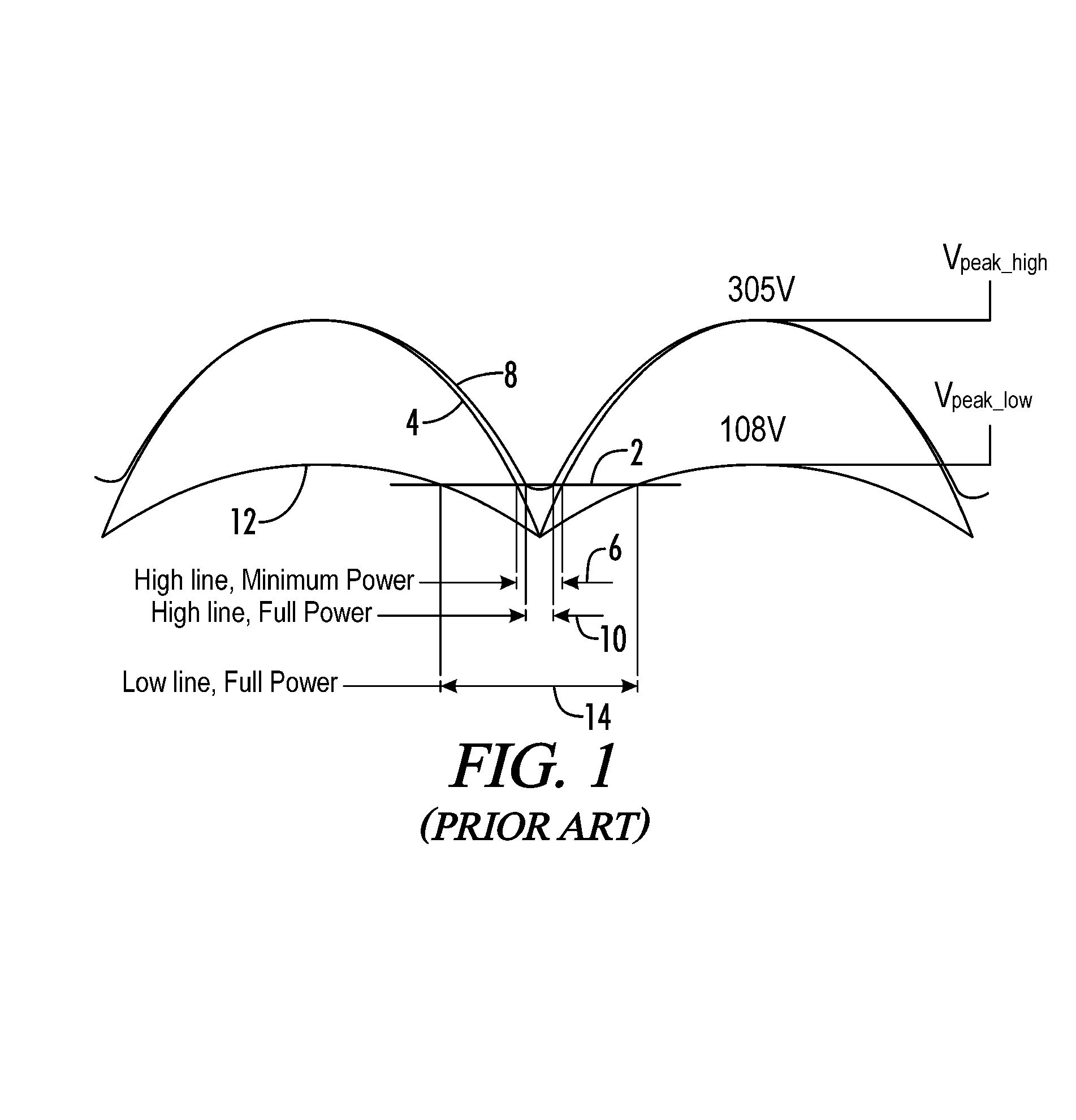
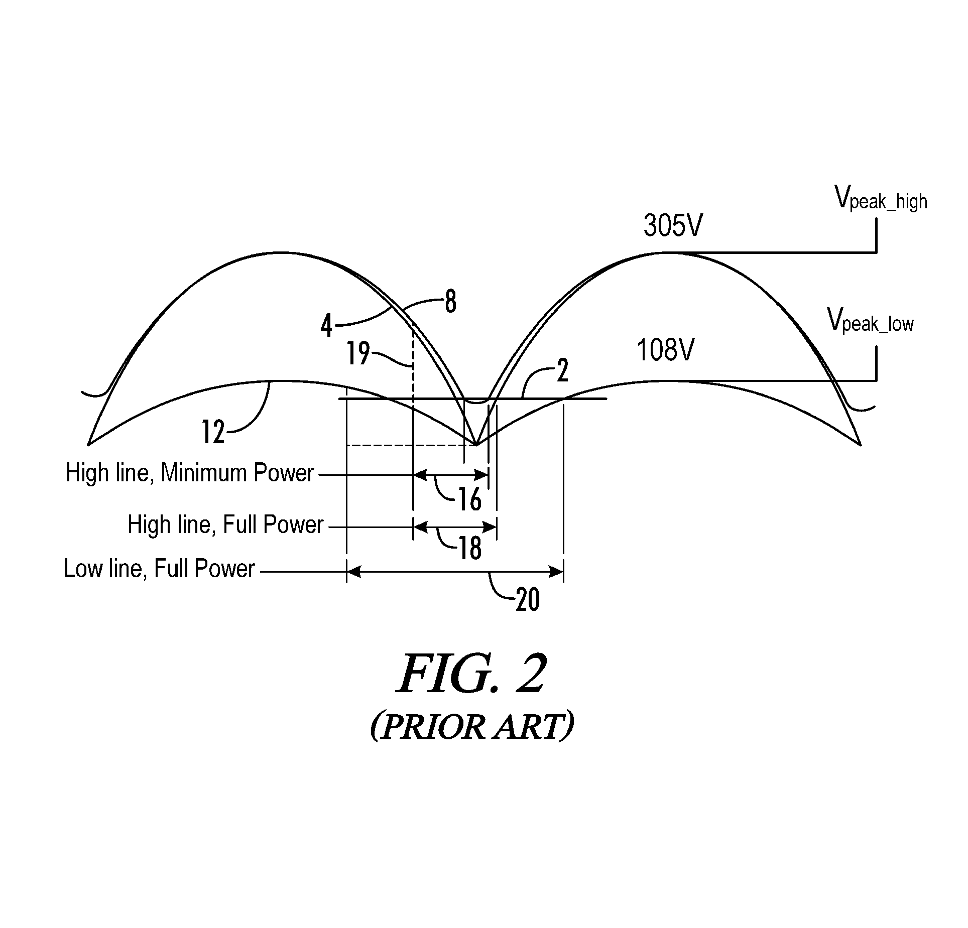
[0016]The idea behind the present invention is to detect predefined phase angles on a sine wave power supply signal independent of the line voltage for use as starting and ending points in generating or detecting a pulse. The peak of the sine wave shaped power signal is referred to as the peak voltage, Vp. Vx is defined as a fraction of the peak voltage of the sine wave that corresponds to a desired phase angle of the sine wave. Thus, the inverse sine of the fraction Vx / Vp gives the angles at which the start and end of the pulse is generated or detected.

θstart=180−sin−1(Vx / Vp)

θend=sin−1(Vx / Vp)

[0017]Theoretically, θstart will be between 90 and 180 degrees for the start of the pulse while θend will be between 0 and 90 degrees. The circuit can be further adapted to receive the input from a current transformer instead of a voltage. This will help to detect the zero crossing of the current and will generate a zero cross pulse that is of substantially constant width at different current l...


PUM


Abstract

A method and apparatus for detecting a zero crossing or desired phase angle of a power line signal having a variable amplitude uses a ratio between a peak amplitude of the power line signal and the amplitude of the power line signal at a desired phase angle for a known amplitude version of the power line signal to detect when a variable amplitude version of the power line signal is at the desired phase angle or zero crossing. The detection of the phase angle is used to determine if a notch is present in the power line signal. A substantially constant width pulse is generated if a notch is detected regardless of the amplitude of the power line voltage or current. The invention is particularly useful in a lighting system for generating and detecting pulses used to communicate information from a power line communication controller to a series of electronic ballasts over a power line used to power the ballasts. The information can be used to control a dimming function of the ballasts.

Description

[0001]This application is a Non-Provisional Utility application which claims benefit of co-pending U.S. Patent Application Ser. No. 60 / 643,694 filed Jan. 13, 2005, entitled “Zero Crossing Detection of Line Voltage / Current of Variable Amplitude” which is hereby incorporated by reference.[0002]Be it known that we, Deepak Shet, a citizen of India, residing in Huntsville, Ala., Changsheng Li, a citizen of China, residing in Madison, Ala., and Jay Dernovsek, a citizen of the United States of America, residing in Madison, Ala., have invented a new and useful “Method and Apparatus for Zero Crossing Detection of Line Voltage / Current of Variable Amplitude.”FIELD OF THE INVENTION[0003]The present invention relates generally to a circuit for producing substantially constant width pulses based upon notches detected in an input AC power line signal having a variable amplitude. More particularly, the invention may be used to detect notches and produce constant width pulses in a ballast communicat...

Claims


Application Information

Patent Timeline
Patent Type & Authority Patents(United States)
IPC IPC(8): H05B37/02
CPCH05B37/0263Y10S315/04H05B47/185
Inventor SHET, DEEPAKLI, CHANGSHENGDERNOVSEK, JOHN JAY
Owner UNIVERSAL LIGHTING TECHNOLOGIES
Why Eureka
Try Eureka