Power generation control apparatus for vehicle

a technology of power generation control and control apparatus, which is applied in the direction of control system, electric generator control, dynamo-electric converter control, etc., can solve the problems of difficult to estimate the accurate torque of the vehicle generator, difficult to perform the optimum control of the exciting current flowing through the exciting winding, and low engine output torque, so as to reduce the voltage drop of the output voltage, minimize the suppression of the exciting current, and maintain the effect of stable rotation speed

Active Publication Date: 2008-07-01
DENSO CORP
View PDF14 Cites 8 Cited by
  • Summary
  • Abstract
  • Description
  • Claims
  • Application Information

AI Technical Summary

Benefits of technology

[0008]It is an object of the present invention to provide an improved power generation control apparatus for a vehicle capable of minimizing a voltage drop of the output voltage of the vehicle generator (or vehicle alternator) caused by the suppression of the torque by increasing the estimation accuracy of the torque of the vehicle generator.
[0010]Thereby, the power generation control apparatus of the present invention is capable of minimizing the suppression of the exciting current flowing through the exciting winding and of decreasing the voltage drop of the output voltage of the vehicle generator even if the power generation control apparatus is in a transient state or unstable state in which the rotation speed of the engine is varied and fluctuated.
[0011]Further, it is preferred that the exciting current control means performs the suppression of the exciting current during the idling condition of the vehicle engine. It is thereby possible to improve and maintain the stable rotation speed of the engine during the idling condition in which the rotation speed of the engine is lower and unstable. It is further possible to prevent the voltage drop of the output voltage of the vehicle generator by halting the suppression of the exciting current during a higher rotation speed of the engine in which the torque of the engine is relatively higher.
[0012]Still further, it is preferred that the exciting current control means halts the suppression of the exciting current while the output voltage of the vehicle generator is lower than a predetermined voltage. If the suppression control of the exciting current is performed when one or more large electrical loads are connected to the vehicle generator to cause a larger voltage drop of not less than a predetermined value of the output voltage of the vehicle generator, namely, to cause that the output voltage of the vehicle generator becomes not more than a predetermined voltage value, there is a possibility to further drop the output voltage of the vehicle generator, and thereby this causes malfunction of the electrical loads of various kinds. Accordingly, it is possible to prevent any occurrence of the malfunction of the electrical loads, which is caused by the voltage drop of the output voltage of the vehicle generator, by halting the suppression operation of the exciting current while the output voltage is lower than the predetermined voltage.

Problems solved by technology

However, when a rotation speed of the engine becomes low, the output torque of the engine becomes low indeed.
However, although the conventional power generation control apparatus disclosed in JP 2003-284257 is capable of estimating the torque of the vehicle generator during a stable rotation speed of the vehicle generator, it is difficult to estimate an accurate torque of the vehicle generator during a varying rotation speed of the engine, and as a result, the conventional technique introduces the voltage drop of the output voltage of the vehicle generator more than necessary and it is thereby difficult to perform the optimum control of the exciting current flowing through the exciting winding.
Thus, the conventional technique involves such a drawback.

Method used


Image

  • Power generation control apparatus for vehicle
  • Power generation control apparatus for vehicle
  • Power generation control apparatus for vehicle

Examples


embodiment

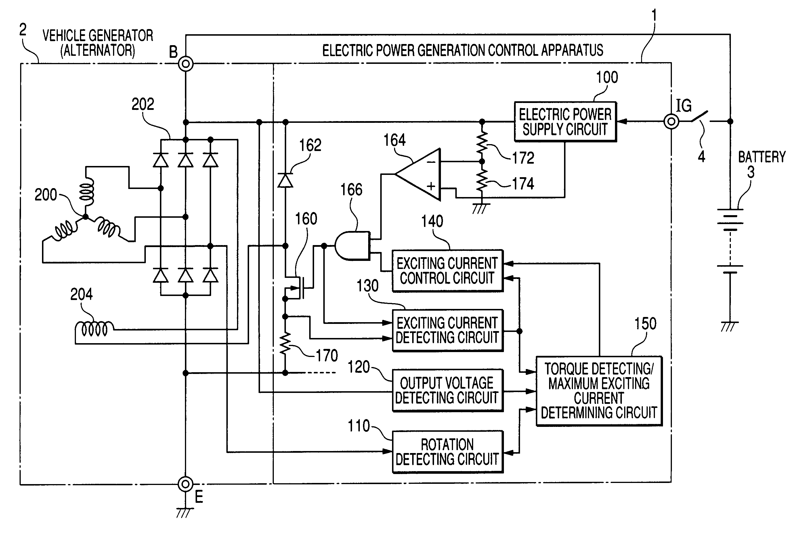
[0023]A description will be given of the power generation control apparatus for a vehicle according to a preferred embodiment of the present invention with reference to FIG. 1 to FIG. 7.

[0024]FIG. 1 is a diagram showing a configuration of the power generation control apparatus for a motor vehicle (or vehicle) according to the embodiment of the present invention. FIG. 1 shows a preferred configuration of the power generation control apparatus 1 for a vehicle, and further shows the connection state between the power generation control apparatus 1, a vehicle generator 2 (or vehicle alternator), and a battery 3.

[0025]In FIG. 1, the power generation control apparatus 1 controls so that a voltage potential at an output terminal B of the vehicle generator 2 has an predetermined regulated set voltage value (for example, 14V). The power generation control apparatus 1 has a power source terminal IG and a ground terminal E in addition to the terminal B. The terminal B is connected to the batte...


PUM


Abstract

A vehicle power generation control apparatus has a power supply circuit, a rotation detecting circuit, an exciting current detecting circuit, a torque detecting / maximum exciting current determining circuit, and an exciting current control circuit. The rotation detecting circuit detects a rotation speed of a generator (or vehicle alternator) and the exciting current detecting circuit detects an exciting current flowing through an exciting winding of the generator. The torque detecting / maximum exciting current determining circuit calculates a power generation torque of the generator based on the output voltage, the exciting current, the rotation speed, and calculates an inertia torque of the generator based on a change rate of the rotation speed. The exciting current control circuit suppresses the exciting current flowing through the exciting winding so that a change rate of a total sum of the generation torque and the inertia torque does not exceed a predetermined value, for example, during the idling condition.

Description

CROSS-REFERENCE TO RELATED APPLICATIONS[0001]This application is related to and claims priority from Japanese Patent Application No. 2005-301559 filed on Oct. 17, 2005, the contents of which are hereby incorporated by reference.BACKGROUND OF THE INVENTION[0002]1. Field of the Invention[0003]The present invention relates to a power generation control apparatus, for use in a motor vehicle (or vehicle), capable of controlling an output voltage of a vehicle generator (or vehicle alternator) to be mounted on the vehicle such as a passenger car and a truck.[0004]2. Description of the Related Art[0005]In the recent years, a motor vehicle (or vehicle) tends to decrease a rotation speed (or rotation number) of a vehicle engine (or engine) mounted thereon during the idling condition as low as possible in order to reduce its fuel consumption. However, when a rotation speed of the engine becomes low, the output torque of the engine becomes low indeed. Thereby, the variation of the driving torqu...

Claims


Application Information

Patent Timeline
Patent Type & Authority Patents(United States)
IPC IPC(8): H02P9/10
CPCH02P9/48H02P2101/45
Inventor UEMATSU, TADASHIASADA, TADATOSHIMAEHARA, FUYUKI
Owner DENSO CORP
Why Eureka
Try Eureka