Heating element for electronic vaporization devices

a heating element and electronic vaporization technology, applied in the direction of ohmic-resistance heating, ohmic-resistance heating details, tobacco, etc., can solve the problems of large liquid drop in the final atomized vapor, undesirable characteristics of the atomizer, non-uniform vapor, etc., to achieve precise resistance, reduce the cost of carbon fiber bundles, and reduce the burden of manufacturing processes

Active Publication Date: 2020-09-03
FONTEM VENTURES
View PDF0 Cites 0 Cited by
  • Summary
  • Abstract
  • Description
  • Claims
  • Application Information

AI Technical Summary

Benefits of technology

The invention is a patent for electronic cigarettes that have a constant output power management system. This system allows for a consistent amount of vaporized liquid during use. This makes it compatible with different types of heating elements which can change the output of the vapor. By adjusting the resistance of the heating element, the system can compensate for changes in output voltage. This is especially useful for heating elements made from fibers, which can have resistances that vary. The use of this system makes it easier to manufacture and reduces the cost of the carbon fiber bundles used in the cigarettes.

Problems solved by technology

Atomizers in electronic smoking devices may have undesirable characteristics, such as poor atomization, large liquid drops in the final atomized vapor, nonuniform vapor caused by different sizes of liquid drops, too much moisture in the vapor, and / or poor mouthfeel, etc.
The decreasing voltage may result in inconsistent puffs.

Method used


Image

  • Heating element for electronic vaporization devices
  • Heating element for electronic vaporization devices
  • Heating element for electronic vaporization devices

Examples


##ic example 2

Prophetic Example 2

[0103]A coil-less atomizer as shown in FIG. 5, prepared according to the process illustrated in FIGS. 8 and 9.

[0104]I) Installation and Optional Sputtering (FIG. 8)

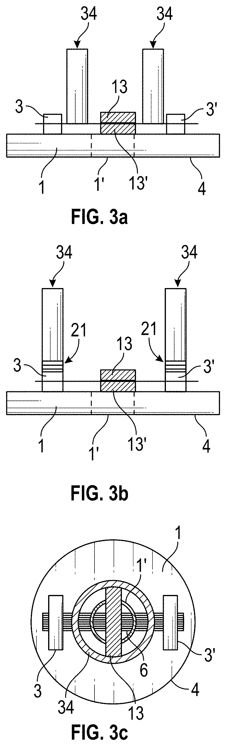
[0105]In this example, fiber material pad 19 made of carbon is shaped by laser cutting or die punching process to provide a shape having first and second fiber material sections and a third fiber material section between the first and second fiber material sections. The diameter of carbon fiber material pad 19 is about 8 mm. The thickness of carbon fiber material pad 19 is about 1 mm. The third fiber material section has a length of about 3 to about 4 mm, and a width of about 1 mm. The first and second fiber material sections have an area of more than three or five times of the area of the third fiber material section. The shaped carbon fiber material pad 19 is installed on board 1, for example a circular PCB, between two metal leads 3 and 3′. Board 1 has a through hole 1′ between leads 3 and 3′. The th...

example 2

ating Element with Decreasing Battery Capacity

[0161]In another example, wet dynamic discharging tests using the dynamic output power management unit of FIG. 10 or 11 were carried out on a wetted heating element, i.e., the resistance of the heating element may change when it has different amount of liquid. The results are shown in FIG. 13. The data lines from the top to the bottom represent the resistance of the heating element in ohms, the battery voltage V, the output energy in J, at 240 mAh, and the discharge time in ms, i.e. the powered time, over testing time in seconds.

example 3

ating Element with Decreasing Battery Capacity

[0162]The results for another set of wet dynamic discharging tests are shown in FIG. 14. The data lines from the top to the bottom represent the resistance of the heating element in ohms, the battery voltage V, the output energy in J at 280 mAh, and the discharge time in ms, i.e. the powered time, over testing time in seconds.

[0163]The power management system described may include dynamic output power management unit for a heating circuit of an electronic smoking device, with the PMU having at least one voltage detection device to detect an output voltage of a power source, and / or a voltage drop across a heating element operable to be connected to or disconnected from the power source via a first switching element, and / or a voltage drop across a reference element operable to be connected to or disconnected from the heating circuit via a change of state of a second switching element from a first state to a second state and from a second s...


PUM


Abstract

An electronic cigarette includes an atomizer having a coil-less heating element having a heating section, two leads electrically connected to the heating section, and a liquid guiding structure. The liquid guiding structure includes two pads, a first pad and a second pad sandwiching at least a portion of the heating section. A gasket may be placed between a liquid supply and the first pad such that liquid is conducted from the liquid supply to the first pad.

Description

CROSS-REFERENCE TO RELATED APPLICATION(S)[0001]This application is a continuation of U.S. application Ser. No. 15 / 571,502, filed Nov. 2, 2017, which is the U.S. National Stage Entry of International Application No. PCT / CN2015 / 078182 filed May 5, 2015. These applications are incorporated herein by reference.BACKGROUND OF THE INVENTION[0002]An electronic smoking device, such as an electronic cigarette (e-cigarette), typically has a housing accommodating an electric power source (e.g. a single use or rechargeable battery, electrical plug, or other power source), and an electrically operable atomizer. The atomizer vaporizes or atomizes liquid supplied from a reservoir and provides vaporized or atomized liquid as an aerosol. Control electronics control the activation of the atomizer. In some electronic cigarettes, an airflow sensor is provided within the electronic smoking device which detects a user puffing on the device (e.g., by sensing an under-pressure or an air flow pattern through...

Claims


Application Information

Patent Timeline
Patent Type & Authority Applications(United States)
IPC IPC(8): A24F40/44H05B3/06H05B3/14A24F40/10A24F40/46
CPCH05B3/06A24F40/44H05B3/145A24F40/46A24F40/10
Inventor YU, FUCHENGLI, ZHUORAN
Owner FONTEM VENTURES
Why Eureka
Try Eureka