Charging circuit with current regulation

a charging circuit and current regulation technology, applied in the direction of electric vehicles, electric power, transportation and packaging, etc., can solve the problem that every power source we can use to charge a device has limited current capabilities in some way, and achieve the effect of reducing and increasing the on-off ratio of the switching modul

Inactive Publication Date: 2015-12-22
SIGNIFY HLDG BV
View PDF20 Cites 2 Cited by
  • Summary
  • Abstract
  • Description
  • Claims
  • Application Information

AI Technical Summary

Benefits of technology

[0005]In view of the current limit of the power source, it would be advantageous to achieve a charging circuit which couples to a power source and which can deliver the maximum current available without surpassing the current limit of the power source to charge an energy storage element, e.g. a supercapacitor, in less time and with greater power efficiency.
[0013]Furthermore, the controlling module will adjust the control signal so as to increase the ON-OFF ratio of the switching module when the input current is substantially smaller than the current limit of the power source. As the ON-OFF ratio of the switching module is increased, more output current flows into the energy storage element and thus the output voltage across the energy storage element rises.
[0014]The controlling module will adjust the control signal so as to decrease the ON-OFF ratio of the switching module when the input current is substantially larger than the current limit of the power source. As the ON-OFF ratio of the switching module is decreased, less output current flows into the energy storage element and thus the output voltage across the energy storage element drops.
[0016]In addition, as for the step-down DC to DC converter, the output current for charging the energy storage element is larger than the input current drawn from the power source as long as the output voltage across the energy storage element is smaller than the input voltage drawn from the power source. As a result, the charging time for the energy storage element is shorter.
[0019]Each energy storage element, e.g. supercapacitor, has a maximum allowed charging voltage and once the charging voltage across the energy storage element is larger than the maximum allowed charging voltage, the energy storage element will be damaged. The charging controlling module can control the storage module to stop charging the energy storage element when the charging voltage across the energy storage element reaches the maximum allowed charging voltage so as to prevent damage to the energy storage element in a more effective way.

Problems solved by technology

Usually every power source we can use to charge a device has limited current capabilities in some way.

Method used


Image

  • Charging circuit with current regulation
  • Charging circuit with current regulation
  • Charging circuit with current regulation

Examples


Embodiment Construction

[0030]Descriptions of embodiments of the present invention are provided in detail hereinbelow, in conjunction with the accompanying drawings.

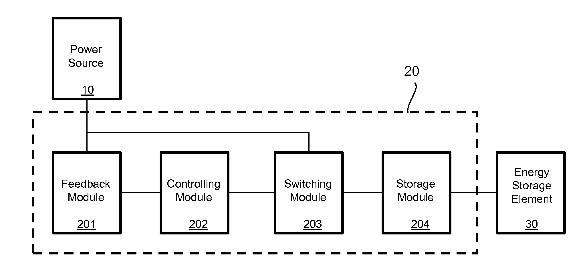
[0031]FIG. 1 illustrates a charging circuit 20 according to an embodiment of the present invention. The charging circuit 20 is coupled to a power source 10 and used for charging an energy storage element 30.

[0032]The power source 10 comprises, but is not limited to, a wall outlet or a USB port.

[0033]The energy storage element 30 comprises, but is not limited to, a supercapacitor or a fast-chargeable Li-Ion battery.

[0034]It is to be noted that any energy storage element which is suitable for very quick recharging could be used in the present invention.

[0035]Referring to FIG. 1, the dashed pane indicates the charging circuit 20 which comprises a feedback module 201, a controlling module 202, a switching module 203 and a storage module 204.

[0036]The feedback module 201 is configured to generate a feedback signal on the basis of the input current d...


PUM


Abstract

The present invention relates to a charging circuit (20) for charging an energy storage element (30). The charging circuit (20) comprises a feedback module (201), a controlling module (202), a switching module (203) and a storage module (204), wherein the controlling module (202) is configured to adjust the control signal so as to increase the ON-OFF ratio of the switching module (203) when the feedback signal is substantially smaller than a reference signal, or to adjust the control signal so as to decrease the ON-OFF ratio of the switching module (203) when the feedback signal is substantially larger than a reference signal. By applying the charging circuit (20), the charging time for the energy storage element (30) is shorter and therefore less power from the power source (10) is consumed.

Description

FIELD OF THE INVENTION[0001]The invention relates to a charging circuit, especially a charging circuit for charging a fast-chargeable energy storage element.BACKGROUND OF THE INVENTION[0002]Supercapacitors have become an upcoming alternative to Li-Ion or NiMH rechargeable batteries. As compared to traditional rechargeable batteries, supercapacitors have the advantages of a very low self discharge, a very low source resistance, more life circles, no danger of fire or explosion and no limit on charging current.[0003]As supercapacitors have the advantage of no limit on charging current, a very quick recharging of a supercapacitor becomes possible by means of increasing the charging current.SUMMARY OF THE INVENTION[0004]Usually every power source we can use to charge a device has limited current capabilities in some way. For example, a wall outlet may have a current limit of 500 or 1000 mA, which it is not allowed to exceed. A USB port, which is often used to charge mobile devices, has ...

Claims


Application Information

Patent Timeline
Patent Type & Authority Patents(United States)
IPC IPC(8): H02J7/00H02J7/04H02J7/34
CPCH02J7/0083H02J7/0055H02J7/045H02J7/0081H02J2007/0062H02J7/345H02J7/00718H02J7/007184H02J2207/40H02J7/00
Inventor SCHNEIDER, GERHARD
Owner SIGNIFY HLDG BV
Why Eureka
Try Eureka