Arrangement for indicating presence of individual

a technology for indicating the presence of individuals and groups, applied in frequency-division multiplexes, instruments, program control, etc., can solve the problems of customer dissatisfaction, instruction is not always followed, and voicemail systems cannot provide the customer with a reliable indication

Inactive Publication Date: 2008-07-01
AMERICAN TELEPHONE & TELEGRAPH CO
View PDF11 Cites 244 Cited by
  • Summary
  • Abstract
  • Description
  • Claims
  • Application Information

AI Technical Summary

Problems solved by technology

However, voicemail systems cannot provide the customer with a reliable indication of whether the employee is in or is reachable in the near future.
Moreover, a voicemail message may not be often checked or the employee may be on vacation, resulting in a delayed return call that causes the customer to be dissatisfied.
However, this instruction is not always followed because it requires the employee to remember to do so.
Moreover, employees may be negligent in checking voicemail, also causing delays that are frustrating to customers who call.
Human error or negligence can thus be responsible for diminishing customer satisfaction.
However, this paging practices requires human intervention, and forces the calling customer to wait, regardless of whether or not the employee responds to the page.
Further, employment of a live central operator increases personnel costs, a result that is contrary to the intent of automated voicemail systems.
U.S. Pat. No. 6,654,815 (Goss et al.) discloses a contact server for a call center in which customers use various communications technologies to submit a call-back request via the Internet; however, Goss' call-back request arrangement does not appear to tell the customer whether the called employee is present or can call back soon.
U.S. Pat. No. 6,574,480 (Foladare et al.) discloses an arrangement for paging an intelligently chosen destination device when a call or other communication is received, based on the identity of a customer and the reason for the communication; however, the Foladare's arrangement does not appear to inherently provide information back to the caller.
U.S. Patent Application Publication No. 2002 / 0145559 (Sullivan) discloses how a person's location may be tracked using a global positioning system (GPS) device; however, Sullivan's device does not solve the larger problem of communicating information about the person's presence to a calling customer.
However, Parsons' arrangement does not appear to tell the caller whether the called person is present or can call back soon.

Method used


Image

  • Arrangement for indicating presence of individual
  • Arrangement for indicating presence of individual
  • Arrangement for indicating presence of individual

Examples


first embodiment

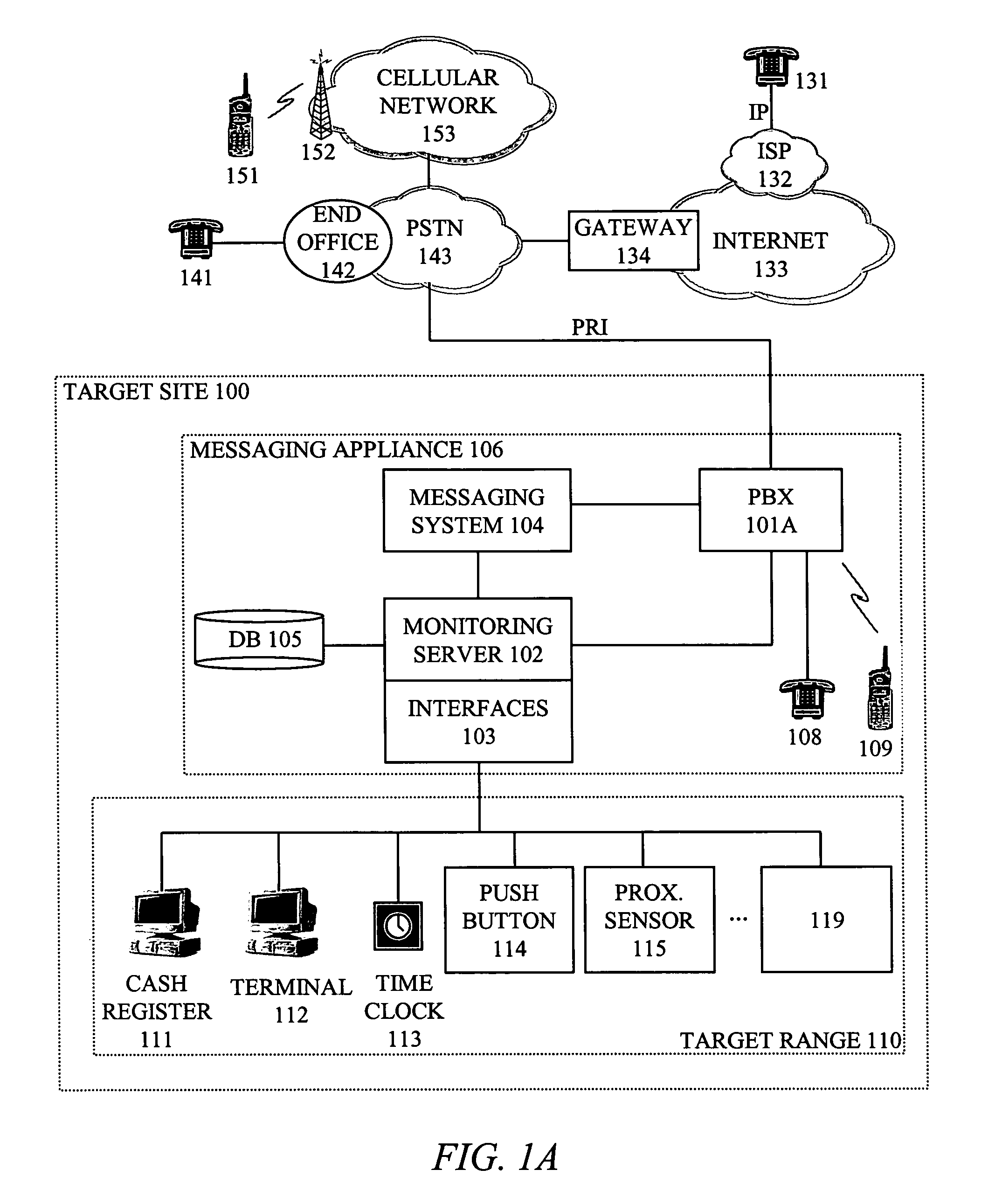
[0030]FIG. 1A illustrates a presence indication arrangement, one involving a primary-rate interface (PRI) between a public switched telephone network (PSTN) and a target site's private branch exchange (PBX).

[0031]For the present discussion it is assumed that a customer desires to contact an employee (“target”) at a store location or enterprise generally indicated as target site 100. The employee is presumed to have an area, called a target range 110, in which roam while he can be contacted by customers or at least indicate that he can be contacted. In the case of most hardware store employees, the target range 110 occupies some or essentially all of a target site 100 because the employee may conceivably roam anywhere in the store but still be contacted.

[0032]A customer using one of telephones 131, 141, 151, and so forth, can call into a target site 100 through a variety of communications media. Assuming that the customer uses telephone technology to contact the target site, the comm...

second embodiment

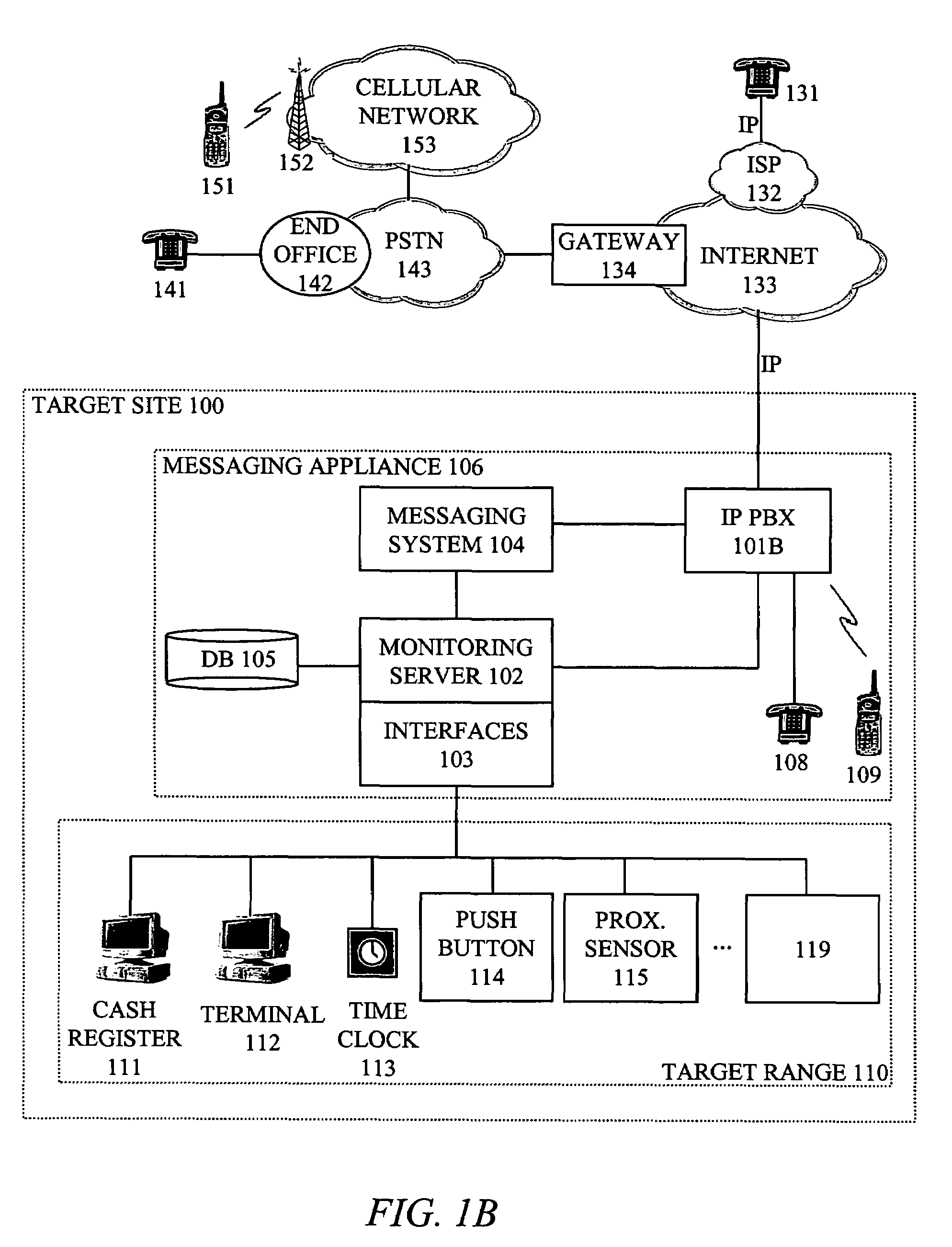
[0069]FIG. 1B illustrates a presence indication arrangement, one involving an internet protocol (IP) interface between an outside network (such as the global Internet) and a target site's IP PBX. FIG. 1B differs from FIG. 1A in that PBX 101A is replaced by IP PBX 101B. Also, IP PBX communicates directly with the Internet 133 via an internet protocol (IP) connection rather than with a public switched telephone network (PSTN) 143 via a PRI connection. The modified architecture merely alters the manner in which communication devices 131, 414, 151, and so forth, communicate with the target site. Thus, FIGS. 1A and 1B collectively demonstrate that a variety of network architectures are envisioned, especially with respect to the manner in which the outside entity (customer) communicates with the target site (enterprise or store).

[0070]The hardware architecture illustrated FIGS. 1A and 1B should not limit the invention. For example, it is envisioned that the PBX could be a centrex located ...


PUM


Abstract

When an entity (such as a customer using a communication device 131, 141, 151 . . . ) attempts to communicate with a target (such as an employee), an arrangement indicates to the customer, “status” information describing at least the employee's present and future ability to communicate with the entity (such as by returning his call). At least one sensing device 111-119 is configured to provide sensing information concerning the target employee's status in response to an action of the target employee with respect to the sensing device. A monitoring server 102 is configured to receive the sensing information and to govern communication to the entity (customer) of the target's “status.” In one implementation, a particular sensing device (such as a cash register 111, computer terminal 112, or time clock 113) is configured to perform both (A) a primary function that is not related to providing the sensing information, and (B) the secondary function of providing the sensing information. In this implementation, the particular sensing device provides the sensing information in response to the person's ordinary use of the particular sensing device as he goes about his job (performing the particular sensing device's primary function), so that the person does not have to explicitly perform any purely presence-related action in order to cause the particular sensing device to communicate the sensing information.

Description

BACKGROUND OF THE INVENTION[0001]1. Field of the Invention[0002]The invention generally relates to arrangements for indicating the presence of a “target” such as an individual. More particularly, the invention relates to arrangements for communicating “status” information describing at least the target's present and future ability to communicate with the entity (such as by returning a call).[0003]2. Related Art[0004]Businesses are always looking for ways to develop better rapport between their employees and their customers, to improve overall customer service. One way of achieving this rapport is to facilitate a customer's communication with a given employee. For example, a customer may wish to easily communicate with a particular plumbing expert at a large hardware store on an ongoing basis. The customer's wish may result from a personal trust, or may be based on the particular employees knowledge or expertise.[0005]Conventionally, businesses provide voicemail service so that custo...

Claims


Application Information

Patent Timeline
Patent Type & Authority Patents(United States)
IPC IPC(8): G05B23/00H04B7/00H04M11/04H04M3/42
CPCH04L63/105H04M3/42374H04L67/24H04W48/08H04L43/0817H04W24/00H04W48/16H04W12/08H04L67/54
Inventor EHLINGER, JAMES C.GILBOY, CHRISTOPHER P.GUDELIS, MARIUS J.
Owner AMERICAN TELEPHONE & TELEGRAPH CO
Why Eureka
Try Eureka