Wireless device reconfigurable radiation desensitivity bracket systems and methods

a technology of radiation desensitivity bracket and wireless device, applied in the field of wireless communication, can solve the problems of counterpoise being susceptible to changes in the design and location of proximal circuitry, affecting radiation pattern and communication efficiency, and affecting radiation pattern and radiation-susceptible circuitry

Inactive Publication Date: 2008-07-01
KYOCERA CORP
View PDF203 Cites 6 Cited by
  • Summary
  • Abstract
  • Description
  • Claims
  • Application Information

AI Technical Summary

Problems solved by technology

Many conventional wireless telephones use a monopole or single-radiator design with an unbalanced signal feed.
However, the counterpoise is susceptible to changes in the design and location of proximate circuitry, and interaction with proximate objects when in use, e.g., placed on a metallic desk, or the manner in which the telephone is held.
As a result of the susceptibility of the counterpoise, the radiation patterns and communications efficiency can be detrimentally impacted.
Even if a balanced antenna is used, so that the groundplanes of proximate circuitry are not required as an antenna counterpoise, radiation pattern and radiation-susceptible circuitry issues remain.
This problem is compounded when an antenna, or a group of antennas operate in a plurality of frequency bands.
It is difficult, if not impossible, to design a wireless device to minimize the interaction between antenna radiation and susceptible circuitry in every one of its communication bands.
As a result, a conventional design must be optimized for one particular communication band, or the design must be compromised to in one or more communication bands of interest.

Method used


Image

  • Wireless device reconfigurable radiation desensitivity bracket systems and methods
  • Wireless device reconfigurable radiation desensitivity bracket systems and methods
  • Wireless device reconfigurable radiation desensitivity bracket systems and methods

Examples


Embodiment Construction

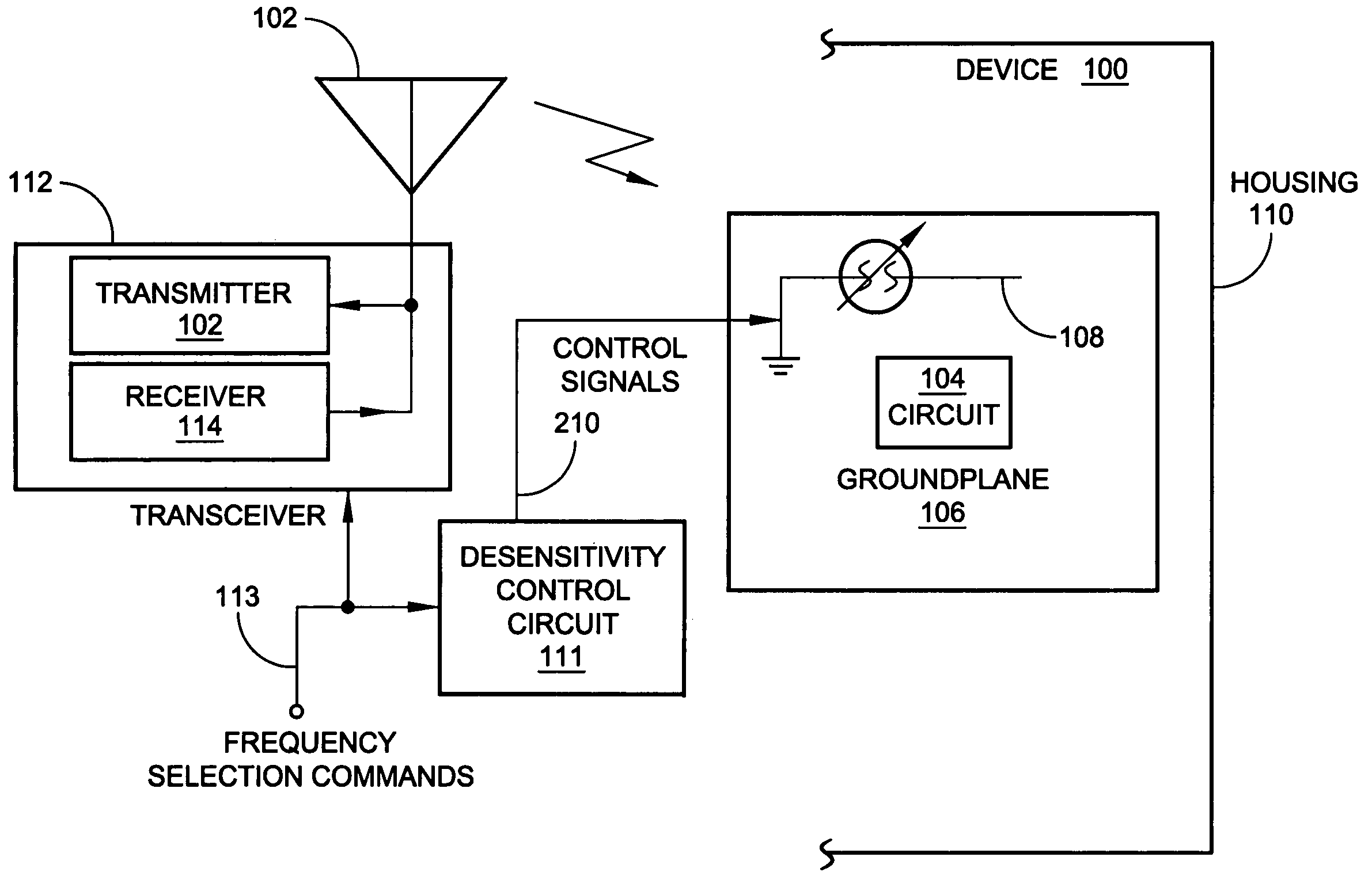
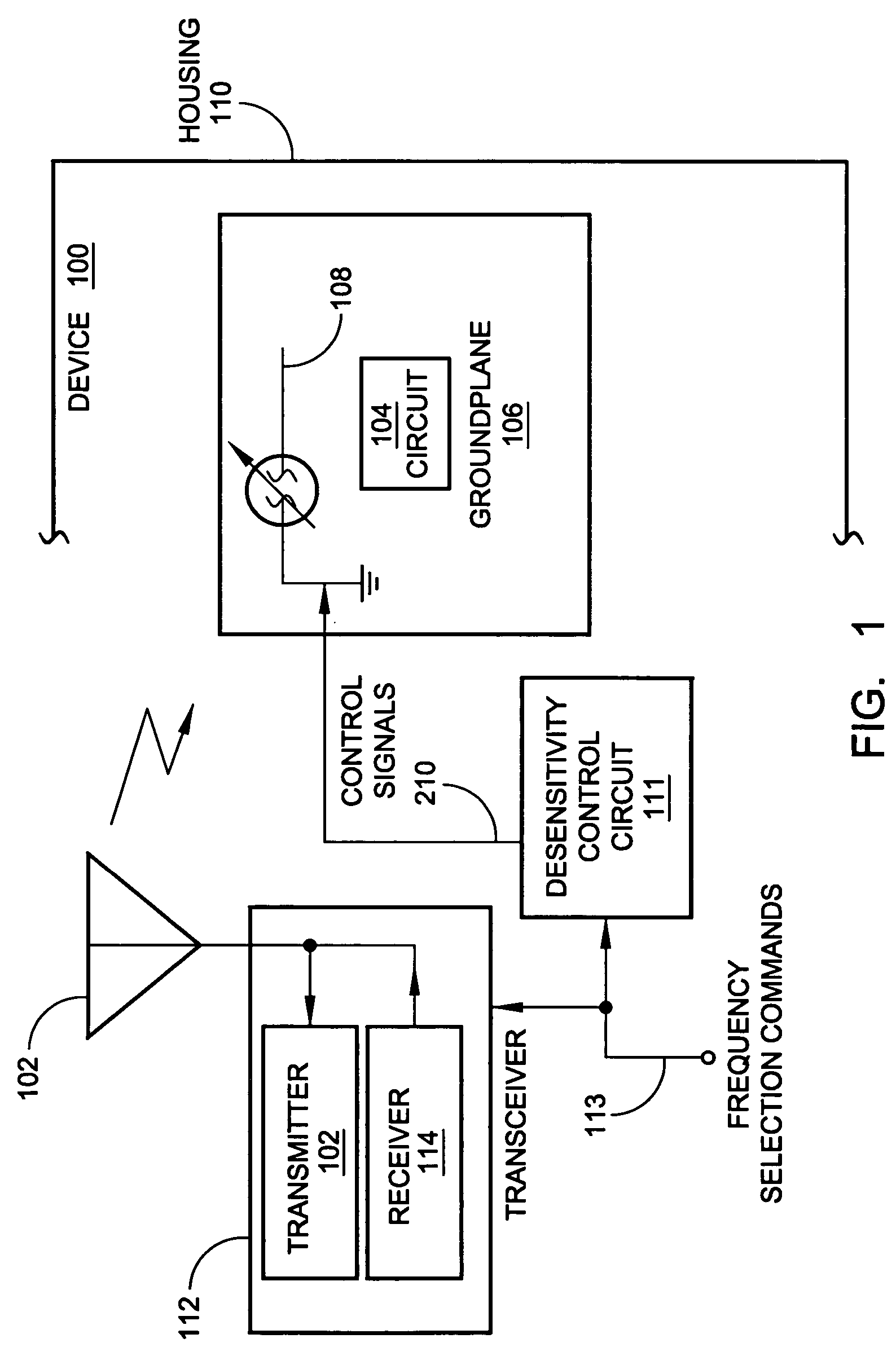
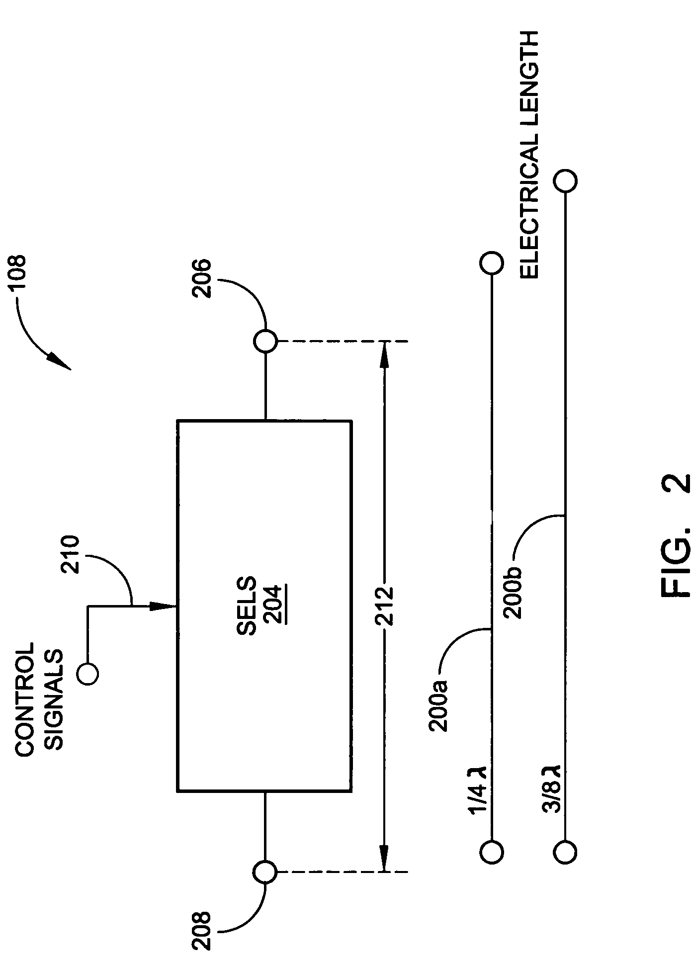
[0031]The present invention describes a wireless communications device with a reconfigurable radiation desensitivity bracket that can be added to the groundplane of a circuit proximate to a radiation source such as an antenna, to minimize the effects of radiation-induced current. The bracket can be selectively tuned or switched in response to changes in frequency. Alternately considered, the bracket is space-reconfigurable to selectively redistribute current flow through the groundplane associated with radiated waves.

[0032]Accordingly, a method is provided for reconfigurable radiation desensitivity in a wireless communications device. The method comprises: generating a radiated wave at a first frequency; in response to generating the radiated wave at the first frequency, creating a maximum current per units square (I / units2) through a minimal area of an electrical circuit groundplane; generating a radiated wave at a second frequency; in response to generating the radiated wave at th...


PUM


Abstract

A wireless communications device reconfigurable radiation desensitivity bracket, and associated reconfigurable radiation desensitivity method are provided. The method includes: generating a radiated wave at a first frequency; in response to generating the radiated wave at the first frequency, creating a maximum current per units square (I / units2) through a minimal area of an electrical circuit groundplane; generating a radiated wave at a second frequency; in response to generating the radiated wave at the second frequency, maintaining the maximum I / units2 through the minimal area of the groundplane. Alternately stated, the method controls the distribution of current flow through a groundplane, responsive to radiated emissions, as the wireless device changes operating frequency or communication band. More specifically, the method maintains the maximum I / units2 through the minimal area of the groundplane by coupling the groundplane to a bracket having a selectable effective electrical length.

Description

RELATED APPLICATIONS [0001]This application is a continuation-in-part application of U.S. application Ser. No. 10 / 775,722, filed Feb. 9, 2004, now U.S. Pat. No. 6,937,195 by Jordi Fabrega-Sanchez, Stanley S. Toncich and Allen Tran, which is hereby incorporated by reference. U.S. application Ser. No. 10 / 775,722 is a continuation-in-part application of U.S. application Ser. No. 10 / 120,603, filed Apr. 9, 2002, now U.S. Pat. No. 6,885,341 by Jordi Fabrega-Sanchez, Stanley S. Toncich and Allen Tran, which is hereby incorporated by reference, which claims the benefit of U.S. Provisional Application 60 / 283,093, filed Apr. 11, 2001, which is hereby incorporated by reference.[0002]In addition, this application relates to the following U.S. applications and patents, which are hereby incorporated by reference: “Reconfigurable Radiation Desensitivity Bracket Systems and Methods”, filed on the same day and having the same inventors as the present application; U.S. Pat. No. 6,690,176, issued Feb....

Claims


Application Information

Patent Timeline
Patent Type & Authority Patents(United States)
IPC IPC(8): H01Q1/24H01G7/06H01P1/203H01P1/213H01P5/04H01Q1/00H01Q3/44H01Q9/04H01Q9/16H01Q9/28H01Q9/30H01Q13/02H01Q13/06H01Q13/20H03B5/18H03B5/36H03F1/56H03F3/191H03H7/01H03H7/12H03H7/20H03J5/24H03L1/02H03L7/18H04B1/30
CPCH01G7/06H04B1/30H01P1/20336H01P1/213H01P5/04H01Q1/00H01Q1/243H01Q3/44H01Q9/0407H01Q9/0421H01Q9/0442H01Q9/16H01Q9/28H01Q9/30H01Q13/02H01Q13/06H01Q13/203H03B5/1841H03B5/362H03F1/56H03F3/191H03H7/20H03J5/246H03L1/022H03L7/18H01P1/203H03F2200/372
Inventor POILASNE, GREGORYFABREGA-SANCHEZ, JORGE
Owner KYOCERA CORP
Why Eureka
Try Eureka