Counter steer detecting method

a detection method and counter steer technology, applied in the direction of steering initiation, instruments, vessel construction, etc., can solve the problems of counter steer detection delay, counter steer detection is inaccurate and easy to be detected, and the differential does not perform the torque distribution to the drive wheels, etc., to achieve accurate and easy detection of counter steer

Inactive Publication Date: 2008-07-01
HONDA MOTOR CO LTD
View PDF61 Cites 14 Cited by
  • Summary
  • Abstract
  • Description
  • Claims
  • Application Information

AI Technical Summary

Benefits of technology

[0009]It is therefore an object of the present invention to provide a counter steer detecting method which can detect counter steer accurately and easily.
[0011]According to the present invention, the counter steer determination area table indicates that the first area where the direction of turn indicated by the steering angle is opposite to the direction of turn indicated by the lateral acceleration is defined outside the counter steer determination area near a point where the steering angle is 0 and the lateral acceleration is 0. In the first area, the sign of the steering angle becomes momentarily different from the sign of the lateral acceleration because of delay characteristics of the vehicle and the lateral acceleration sensor in slalom running or the like. However, it is determined that the counter steer is off in this first area, thereby preventing improper determination of the counter steer.
[0012]Further, the counter steer determination area table indicates that the second area where the direction of turn indicated by the steering angle is the same as the direction of turn indicated by the lateral acceleration is defined inside the counter steer determination area where the lateral acceleration is larger than a boundary value increasing in absolute value from a first predetermined value greater than 0 at a steering angle of 0 with an increase in absolute value of the steering angle. Accordingly, when the direction of steer becomes opposite to the direction of turn of the vehicle and the lateral acceleration remarkably delays in response to the steering angle, it is determined that the counter steer is on in this second area, so that the counter steer can be early detected.
[0014]The accuracy of determination of the counter steer can be improved by increasing the number of tables in the case that the tables are selectively used according to the vehicle speed detected by the vehicle speed sensor. On the other hand, in the case that the predetermined table using a corrected steering angle obtained by correcting the steering angle detected by the steering angle sensor with a correction coefficient according to the vehicle speed detected by the vehicle speed sensor is adopted as the counter steer determination area table, the table can be easily prepared and the counter steer can be accurately detected.
[0016]When the combination of the steering angle detected by the steering angle sensor and the lateral acceleration detected by the lateral acceleration sensor stays inside the counter steer determination area for a predetermined time period, the on state of the counter steer is determined. Accordingly, it is possible to prevent improper determination due to sensor noise or the like and hunting of counter steer detection / cancellation.
[0018]When the combination of the steering angle detected by the steering angle sensor and the lateral acceleration detected by the lateral acceleration sensor stays outside the counter steer determination area for a predetermined time period, the off state of the counter steer is determined. Accordingly, it is possible to prevent improper determination due to sensor noise or the like and hunting of counter steer detection / cancellation.

Problems solved by technology

However, when one of the right and left drive wheels slips, torque distribution to the drive wheels by the differential is not performed.
First, until the direction of steer becomes opposite to the direction of turn of the vehicle, the counter steer cannot be detected, so that the detection of the counter steer is delayed.
Secondly, the sign of the steering angle becomes momentarily different from the sign of the lateral G because of delay characteristics of the vehicle and the lateral G sensor in slalom running or the like, and the counter steer is improperly determined in spite of the above case where no counter steer occurs.
First, since the counter steer is detected according to the magnitude of the actual lateral G detected by the lateral G sensor and the magnitude of the calculated lateral G, it is difficult to determine the correlation between the counter steer and the magnitudes of the actual lateral G and the calculated lateral G, so that accurate detection of the counter steer is difficult.
Secondly, until the direction of steer becomes opposite to the direction of turn of the vehicle, the counter steer cannot be detected, so that the detection of the counter steer is delayed.

Method used


Image

  • Counter steer detecting method
  • Counter steer detecting method
  • Counter steer detecting method

Examples


Embodiment Construction

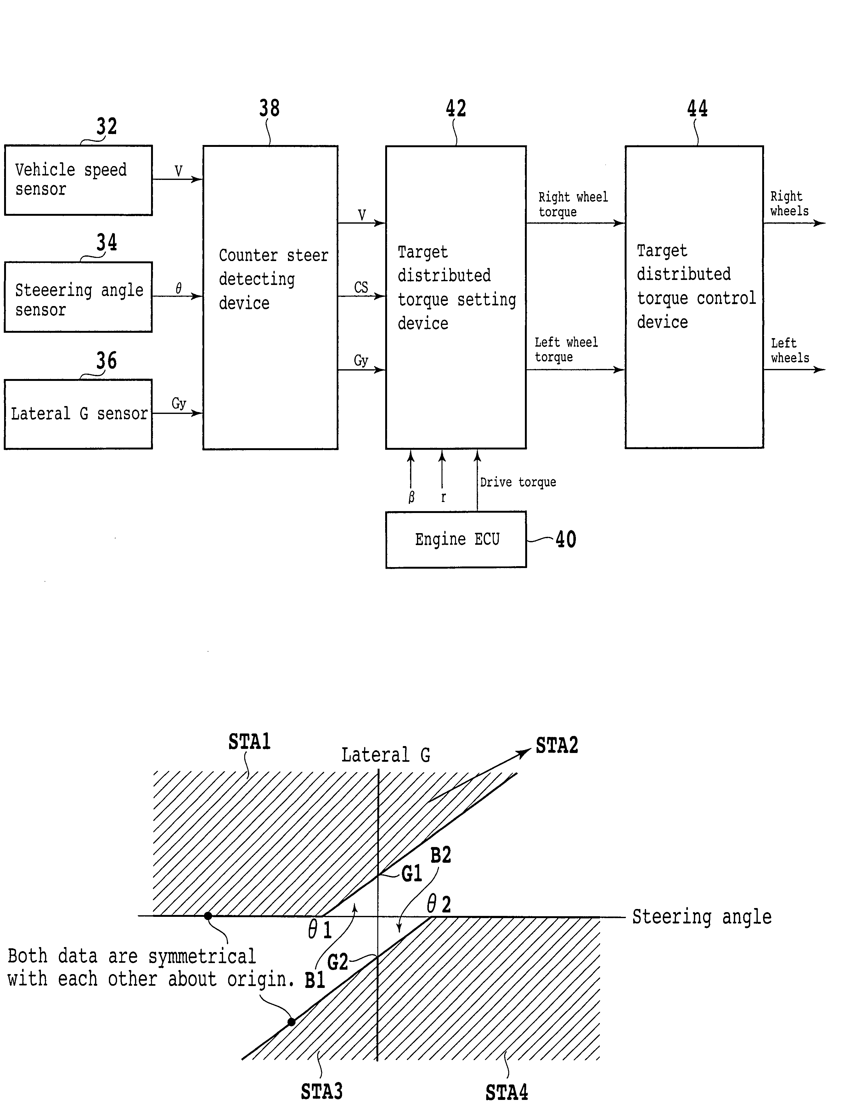
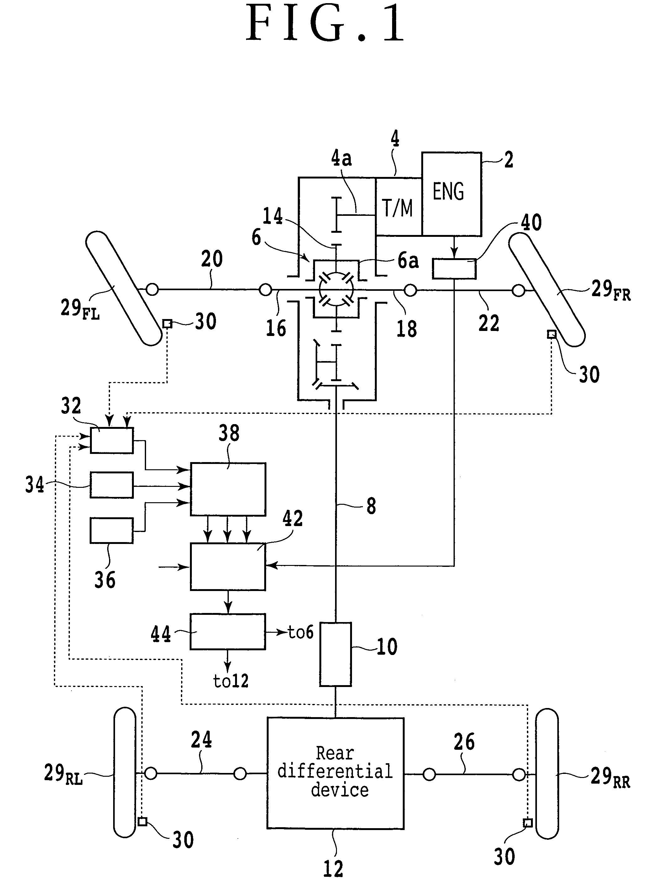
[0027]FIG. 1 is a schematic diagram of a power transmitting system for a four-wheel drive vehicle based on a front-engine front-drive (FF) vehicle to which the counter steer detecting method of the present invention is applicable. As shown in FIG. 1, the power transmitting system mainly includes a front differential device 6 to which the power of an engine 2 located at a front portion of the vehicle is transmitted from an output shaft 4a of a transmission 4, a speed increasing device (speed changing device) 10 to which the power from the front differential device 6 is transmitted through a propeller shaft 8 extending in the longitudinal direction of the vehicle, and a rear differential device 12 to which the power from the speed increasing device 10 is transmitted.

[0028]The front differential device 6 has a structure well known in the art, and the power from the output shaft 4a of the transmission 4 is transmitted through a plurality of gears 14 and output shafts 16 and 18 in a diff...


PUM


Abstract

The counter steer detecting method includes the steps of detecting a steering angle by a steering angle sensor, detecting a lateral acceleration by a lateral acceleration sensor, and determining counter steer according to the steering angle detected by the steering angle sensor and the lateral acceleration detected by the lateral acceleration sensor on the basis of a counter steer determination area table indicating whether or not the counter steer is on in relation to the combination of steering angle and lateral acceleration.

Description

BACKGROUND OF THE INVENTION[0001]1. Field of the Invention[0002]The present invention relates to a counter steer detecting method, and more particularly to a method of detecting counter steer accurately and early.[0003]2. Description of the Related Art[0004]The turning performance of a vehicle can be improved by providing a differential for controlling the difference in torque between right and left drive wheels. However, when one of the right and left drive wheels slips, torque distribution to the drive wheels by the differential is not performed. Accordingly, it is necessary to control the torque distribution according to a running condition of the vehicle. In a four-wheel drive vehicle, the difference in torque between front and rear wheels is controlled to improve both the turning performance and the running stability of the vehicle.[0005]In general, when the differential action of a differential is limited, the running stability is improved, whereas when the differential action...

Claims


Application Information

Patent Timeline
Patent Type & Authority Patents(United States)
IPC IPC(8): B62D5/04B62D6/00
CPCB60K28/14B60W30/02B60G2800/016B60W2720/30B60G2800/244B60G2800/952B60G2800/96B60W10/02B60W10/20B60W30/045B60W2510/20B60W2520/10B60W2520/125B60W2710/0666B60W2710/12B60G2800/213B60W30/18145B60W2540/18
Inventor MORI, ATSUSHI
Owner HONDA MOTOR CO LTD
Why Eureka
Try Eureka