
Power tool

a technology of power tools and operating parts, which is applied in the direction of portable power-driven tools, manufacturing tools, drilling machines, etc., can solve the problems of difficult contact between the tool resting surface, and the user's fingers are difficult to inadvertently touch so as to avoid any erroneous actuation of the stopper operating portion, prevent any damage, and simple construction

Inactive Publication Date: 2008-07-08
MATSUSHITA ELECTRIC WORKS LTD
View PDF11 Cites 14 Cited by
  • Summary
  • Abstract
  • Description
  • Claims
  • Application Information

AI Technical Summary

Benefits of technology

"The present invention provides a power tool with a stopper portion that can limit the pulling amount of the trigger and prevent accidental actuation. The tool includes a grip portion, a main body, a motor, an output portion, a speed control switch, a stopper operating portion, and a battery receiving portion. The stopper operating portion is designed to make contact with the trigger and limit its movement. The tool is also designed to prevent damage to the stopper operating portion when dropped or placed on a tool resting surface. The invention also provides an auxiliary spring and a retaining member to keep the stopper portion in a specific position. The mobile member of the tool can be moved smoothly along a slant guide groove and the position of the stopper portion can be adjusted to control the maximum pulling amount of the trigger and the maximum rotation speed of the motor."

Problems solved by technology

This makes it difficult for the user's fingers to inadvertently touch the stopper operating portion when the grip portion is initially grasped or continues to be in a grasped condition.
Thus, it is hard for the stopper operating portion to make contact with a tool resting surface even if the power tool is placed on the tool resting surface when not in use.

Method used


Image

  • Power tool
  • Power tool
  • Power tool

Examples


Embodiment Construction

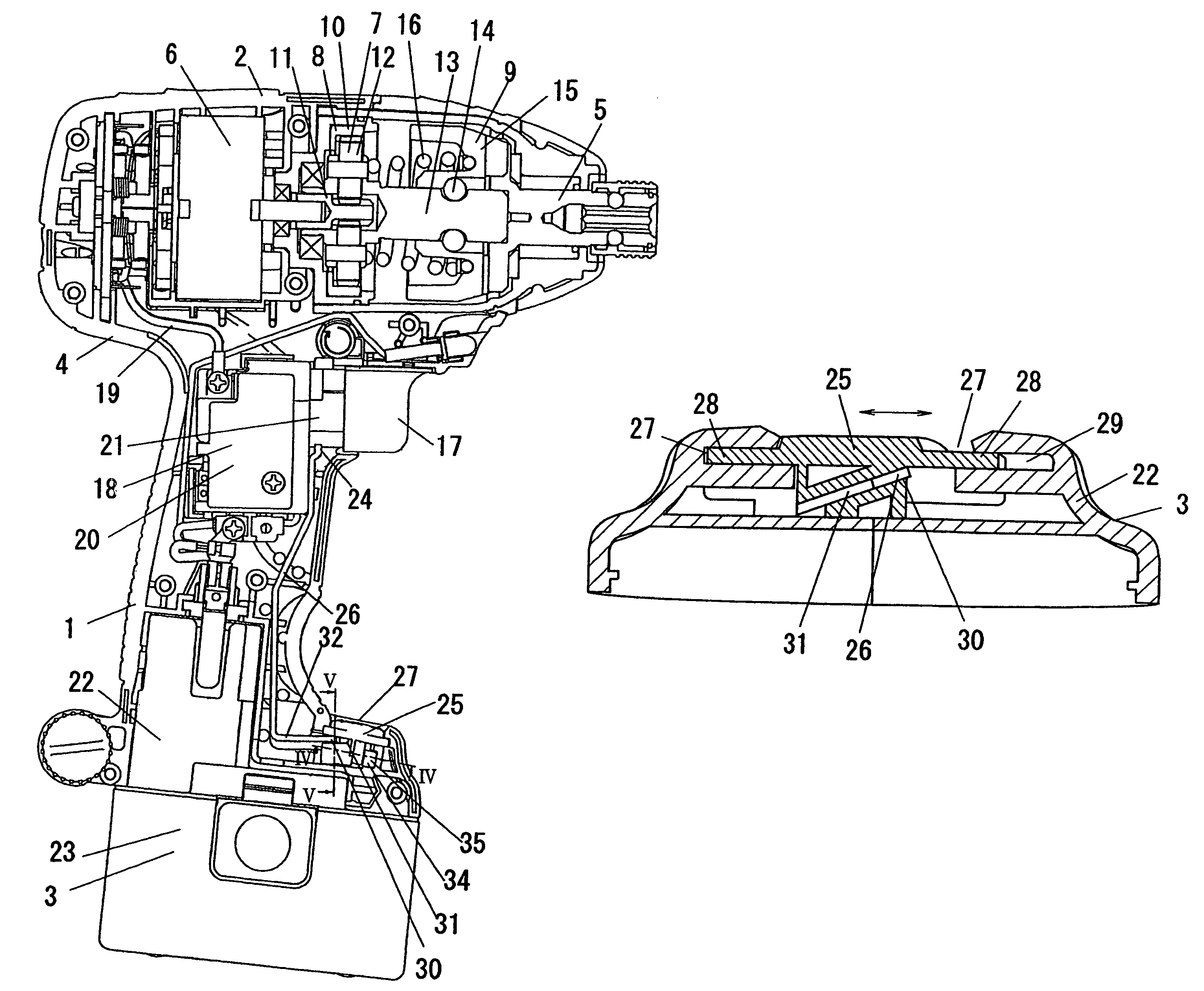
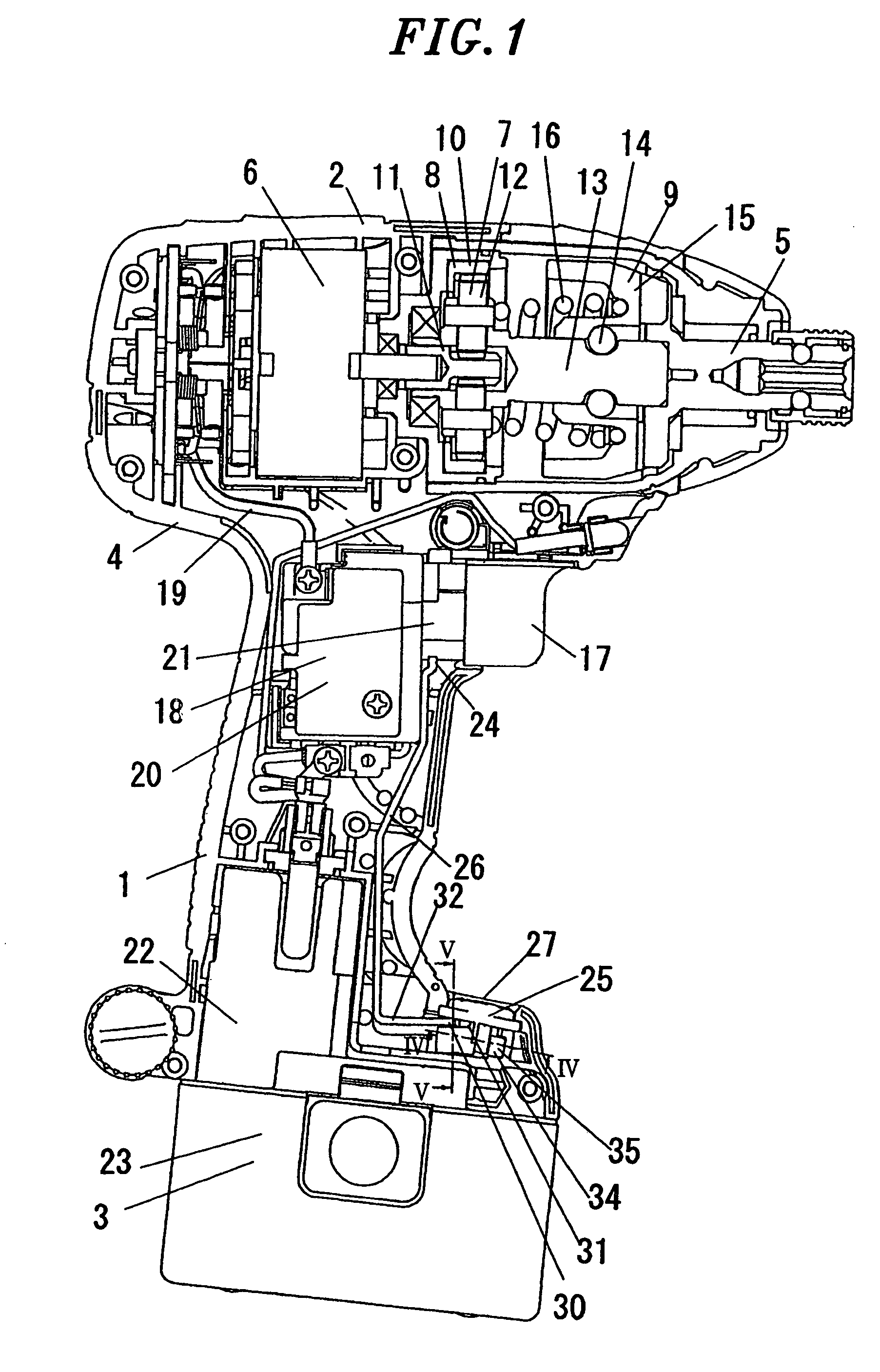
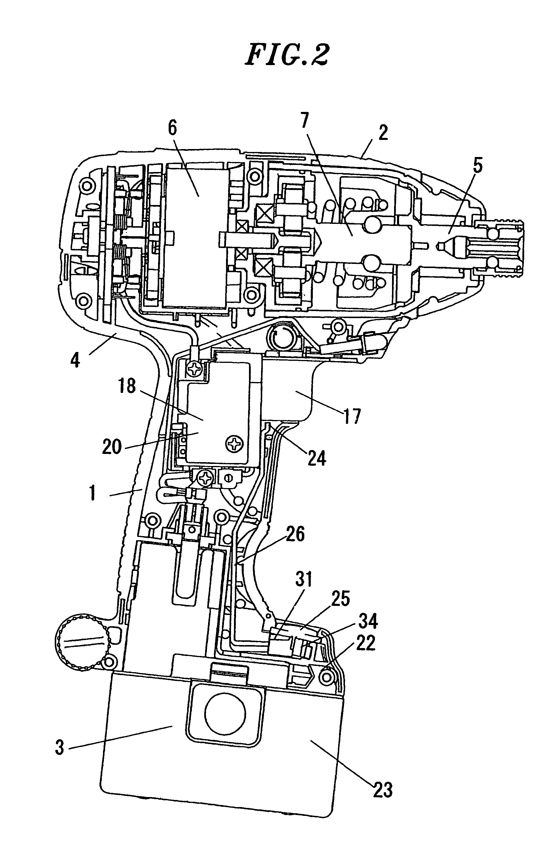
[0030]Hereinbelow, the invention will be described with reference to the accompanying drawings in terms of exemplary embodiments. The power tool shown in FIGS. 1 through 6 is a rotary impact tool that can be used as a hand-held impact driver or a hand-held impact wrench.

[0031]Referring to FIG. 1, the power tool includes a generally round tubular hollow grip portion 1, a generally round tubular main body 2 provided at one axial end of the grip portion 1 with its axis intersecting the axis of the grip portion 1, and a battery receiving portion 3 provided at the other axial end of the grip portion 1 opposite to the main body 2. The respective outlines of the grip portion 1, the main body 2 and the battery receiving portion 3 cooperate with one another to form a housing 4. In the following description, the axial direction of the grip portion 1 will be referred to as “up-down” or “vertical”, the axial end side of the grip portion 1 at which the main body 2 lies will be called “upper” or ...


PUM

PropertyMeasurementUnit
rotation speedaaaaaaaaaa
dimensionaaaaaaaaaa
heightaaaaaaaaaa

Abstract

A power tool includes a grip portion having a vertically extending axis; a main body provided at a top end of the grip portion and having an axis intersecting the vertical axis; a motor; an output portion projecting from the grip portion and rotatingly driven by the motor; a trigger provided for movement along a trigger moving zone; a stopper portion accommodated in the grip portion for protrusion and retraction into and from the trigger moving zone, the stopper portion adapted to selectively make contact with the trigger to thereby limit the maximum pulling amount of the trigger; and a stopper operating portion for operating the stopper portion. The stopper portion is protruded into or retracted from the trigger moving zone by slidingly actuating the stopper operating portion in a crosswise direction perpendicularly intersecting the axis of the main body as viewed from the top.

Description

FIELD OF THE INVENTION[0001]The present invention relates to a power tool having a built-in speed control switch for controlling the rotation speed of a motor depending on the pulling amount of a trigger.BACKGROUND OF THE INVENTION[0002]Examples of power tools used in tightening bolts or screws or drilling holes include a hand-held type power tool that has a grip portion whose axis extends in an up-down direction 3nd a main body provided on the to, end of the grip portion, the main body having an axis intersecting the axis of the grip portion such that the power tool can have a generally T-shaped or L-shaped configuration as a whole. As one example of this kind of power tool, Japanese Patent Laid-open Publication No. S60-196904 (“prior art reference 1”) discloses a power tool having a trigger provided on the top of a grip portion for movement along the axial direction of a body and a built-in speed control switch for controlling the rotation speed of a motor depending on the pulling...

Claims


Application Information

Patent Timeline
Patent Type & Authority Patents(United States)
IPC IPC(8): B25D11/00B25D11/04
CPCB25F5/001
Inventor NAKAMURA, MASAMICHIOKADA, YOSHIKAZU
Owner MATSUSHITA ELECTRIC WORKS LTD
Learn More